
Subscribe to Our Youtube Channel
Summary of Contents for Orbit Controls OC 7040A-POL
- Page 1 7040A-POL_GBM_21002 DIGITAL LINEARIZER OC 7040A- POL Owner’s Manual ORBIT CONTROLS AG Zürcherstrasse 137 CH-8952 Schlieren/ZH Tel: + 41 44 730 2753 Fax: + 41 44 730 2783 info@orbitcontrols.ch www.orbitcontrols.ch...
- Page 2 Vor dem Einschalten Überzeugen Sie sich, ob Ihre Sendung das richtige Gerät Orbit Controls Modell OC 7040A-POL beinhaltet, einschliesslich einer Betriebsanleitung OC 7040A-POL. Vor dem Einschalten des Gerätes überprüfen Sie die Anschlüsse und die Versorgungsspannung. Ein falsch angeschlossenes Gerät kann beschädigt werden und damit auch die mitverbundene Folgeelektronik.
- Page 3 INDEX Page PROGRAMMABLE DIGITAL LINEARIZER OC7040-POL SPECIFICATIONS TERMINALS Rear Panel Option Card Serial Ports RS232 and RS485 Analogue Outputs Relay Outputs KEYBOARD ASSIGNEMENT of the INPUT SIGNAL to DISPLAY MENU STEPS POLYNOM-LINEARIZING CALIBRATION Calibration of linear Signals DC and AC Calibration of non-linear Signals 7.2.1 Calibration of Pt-100 Thermometers 7.2.2 Calibration of Thermocouples...
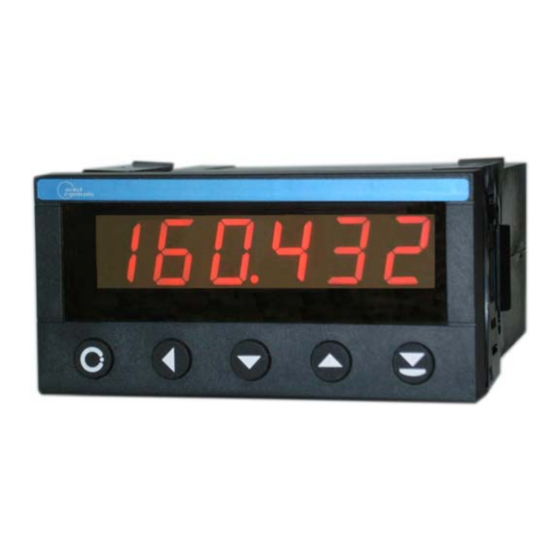
- Page 4 PROGRAMMABLE DIGITAL LINEARIZER OC 7040A - POL 6 Digit Display ± 999999 ± 100 000 Measuring Increments Input 4-20mA, 0-1V, 0-10V Strain Gauge 20mV Polynom 6the Degree Free programmable Four Set Point Relays RS 232 and RS 485 Isolated Excitation Output 0/4-20mA, 0-10V OC7040A-POL is a programmable 6 digit instrument with inputs for process signals such as 0-20mA, 4- 20mA, 0-1V, 0-10V, -1V...+1V und -10V...+10VDC and 20mV Strain Gauge Applications.
- Page 5 Four Set Points can be set within the entire display range 0…± 999999. They activate four output transistors or four mechanical Relays. The hysteresis can be individually programmed. Input is designed for signals 0 ... ± 1V, 0 ... ± 10 V or 0/4-20mA. For Strain Gauge applications a programmable range is also available.
-
Page 6: Specifications
SPECIFICATIONS 0 ... ± 999999, 7 segment red LED, 14.7mm with decimal points. Display: Input: The input is configured upon the customer order for DC or AC voltage or current, RTD or Thermocouples, Potentiometers, Resistors or Strain Gauge. ± 100mV to 300V DC or true RMS. Voltage 20mVDC for Strain Gauges 0/4-20mA, ±20mA to 5A DC or true RMS. - Page 7 TERMINALS REAR Panel of the instrument RS232 – Request Transmission RS232 – Continuous Transmission Option Card Two analogy outputs, two serial data ports and four set point relays are optionally available. The option card is placed in the upper part of the cabinet. The card contains two analogy outputs 4-20mA and - 10…+10V and two data ports RS232 and RS485.
- Page 8 Serial Ports RS232 and RS485 The Baud Rate can be set in the menu Step bAUd with keys UP or DOWN, the address in rS Adr. The address 00 automatically activates RS232. One of addresses 01 ... 31 activates RS485. Data Format: 8 bit, No Parity, 1 Start und 1 Stop, Baud Rate 1200 to 19200.
- Page 9 KEYBOARD MENU DOWN 1,2,3,4 activated Set Points Program Mode The key MENU opens the menu. The required parameter will be confirmed with ACK and set with UP or DOWN. The flashing digit - Cursor - can be positioned with ACK. The sign and the decimal point can be set when the cursor is moved out of the display range and no digit is flashing.
-
Page 10: Menu Steps
MENU STEPS The text bellow shows the full menu with all options installed. If one or more options are not installed, the corresponding menu Step is suppressed in the menu. The key MENU permits the entry into the menu and scrolling the parameters at the display. The required menu step will be confirmed with ACK. The Cursor (flashing digit) can be moved with ACK and set with UP or DOWN to required value. - Page 11 MENU Aout L Display value for Analogue Output 0 (-10) V and 0/4mA MENU Aout H Display value for Analogue Output 10V and 20mA The outputs 0 or 4mA and 0V or -10V can be selected at the Option Board. MENU SEnS Selection of the Input Type...
- Page 12 POLYNOM – LINEARIZING The Polynom-Linearizing will be activated in the Menu. A polynom of sixth degree can be used. The Polynom contains 7 coefficients: coef0 cee0 to coef6 coee6, whereas the Index is the Exponent which multiplies the measured value. It will also be multiplied by a tenth power which is entered as coee. The coefficients have 6 digits with decimal point and sign, the exponents can be set from 0 to ±...
- Page 13 CALIBRATION Calibration of linear signals DC and AC The calibration of linear signal such as 4-20mA, 0-1V is described in § 10, Service Menu-HtESt. Calibration of non-linear signals (Tables) Following is the calibration of non-linear signals derived from internally memorized function tables: 7.2.1 Calibration of Pt-100 Thermometers SEnS LinEAr...
- Page 14 Selection of Measuring Range Jumper 20mA 100V selection 10mV-1V Z8 , Z9 DC= Z8 closed, Z9 open AC= Z8 open, Z9 closed R19 (§ 7.3) open open open open R=50k/G-1 Input single ended (+)15, (-)14,13 (+)15, (-)14,13 (+)15, (-)14,13 (+)15, (-)14,13 (+)15, (-)14,13 Input differential (+)15, (-)13...
- Page 15 Selection of Mains Voltage 115/230VAC 115VAC solder blobs X2, X3 230VAC solder blob X1 X1 = open X2 = X3 = open...
- Page 16 EXAMPLES Process Signal 0/4-20mA Two Terminals Sensor RTD Thermometer and Ohmmeter Thermocouples and Thermistors Differential Inputs Strain Gauges...
- Page 17 SERVICE MENU - HtESt The service menu HtESt permits checking of the display, setting of optional parameters and calibration of the signal channel. The service menu will start when the key MENU is kept pressed while the power is switched-on. The test of the display segments is performed, the HCF parameter can be set (see bellow) the signal channel can be calibrated, the Set Points activated and the Analogue Output signals generated.
- Page 18 BURST TEST and RECOMMENDED GROUNDING Tester: Burst-Surge Generator HILO, Model CE-Tester E.U.T.: OC7040, SN: 980315, Supply 230VA Mode: Linear, Set LO = 000000, Set HI = 10000 Input: 4-20mA Display: 10 000 10.1 Test Conditions According to: IEC 801-4 IEC 1000-4-4 EN 50052-1 10.2 Test Set - Up...
Need help?
Do you have a question about the OC 7040A-POL and is the answer not in the manual?
Questions and answers