Advertisement
Quick Links
Electronics for Model Railroads
GENERAL DESCRIPTION:
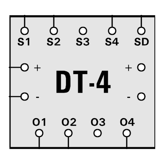
TORTOISE Switch Machine when used in conjunction with a CIRCUITRON Detection Circuit such as the DT-4.
Both units may be powered from any 12-18 volt DC source and the output terminals directly connect to the
TORTOISE machine.
The TC-3 has two control terminals and may be used to independently control both directions of a turnout. In
this way, the output from one detection circuit may be used to throw the TORTOISE one way, and the output
of another detection circuit used to throw it back. The TC-3 is also ideal as an interface circuit when it is
desired to activate TORTOISE Switch Machines from momentary panel pushbuttons or through diode matrix
control. One TC-3 is required for each TORTOISE to be thus controlled.
The TC-4 is CIRCUITRON's TORTOISE Turnout Direction Alternator. It contains only one control terminal.
When the control terminal is connected to a detection circuit, the TORTOISE will be thrown one way the first
time a train is detected, and then will be thrown the opposite way the next time a train is detected. In this
way, trains can be made to automatically travel alternate routes each time around a layout.
CIRCUIT DESIGN:
Both the TC-3 and TC-4 utilize CMOS logic circuit outputs to directly drive the TORTOISE
Slow Motion Switch Machine. An input diode provides reverse polarity protection and the DC is filtered and
regulated to 12 volts by an on-board IC regulator. The TC-3 uses a quad NAND gate package wired as a set-
reset (R-S) flip-flop. A ground on either control terminal will set or reset the flip-flop. The output is buffered by
the remaining two gates and applied to the output terminals where reverse series wired zener diodes clamp any
high voltage transients from the TORTOISE motor and prevent damage to the IC. The TC-4 utilizes a dual D
flip-flop package with one flip-flop configured in the toggle mode and the second acting as a slave R-S flip-flop
to buffer the output. Additional conditioning is provided on the Control terminal input of the TC-4 by a schmitt
trigger package to prevent false triggering of the circuit. Outputs are zener protected as on the TC-3.
INSTRUCTIONS:
The TC-3 and TC-4 can be connected with .110" x .032" solderless connectors (available from
CIRCUITRON) or by soldering leads directly to the terminals on the printed circuit board. If soldering, use a small
pencil-type iron and electronics-grade rosin core 60/40 solder (available from Radio Shack). Use only as much heat
as necessary to obtain a good joint and do not wiggle the terminal until the solder has cooled completely. A section
of CIRCUITRON'S PCMT can be used for simple, snap-in mounting of the circuit board or you may drill holes in the
mounting pads in the corners of the board and mount the TC-3 and TC-4 with screws and standoffs.
1) Mount the circuit board in a convenient location. Connect two light (22-24) gauge stranded wires to
terminals 1 and 8 on the TORTOISE and run them to the [OUTPUT] terminals on the TC-3 or TC-4. If you
are wiring a TC-3, make the connections at the circuit board temporary at this time.
2) Connect the Control Terminals ([C1] and [C2] on the TC-3, [C] on the TC-4) to the output of any
CIRCUITRON Detection Circuit (the DT-4 is ideal for this application) using the same type wire as above.
The Opto-Sensor supplied with the Detection Circuit should be located at the point where it is desired to
have the TORTOISE activated.
so that the TORTOISE can complete its throw before the train arrives.
3) Connect a source of 12-18 volts DC to the [INPUT] terminals. Observe proper polarity.
4) If your input voltage is from a regulated 12 volt source such as our PS-2 or PS-2A, losses in the Turnout
Control Circuit will result in an output voltage to the TORTOISE of 9 volts or less. If the reduced speed
of the TORTOISE is objectionable, the on-board voltage regulator may be bypassed by connecting a short
length of wire between the two terminals labelled [BYPASS].
connection unless you are ABSOLUTELY certain your power supply is REGULATED at 12 volts DC. The
DC accessory terminals on a power pack are NOT regulated. Making this connection will subject the
CMOS IC(s) to the full supply voltage without protection and damage to the IC(s) is not covered by
warranty under these conditions.
5) Test the operation under power and confirm that the turnout is being thrown in the correct direction (TC-
3). If not, reverse the leads connected to the [OUTPUT] terminals. Finally, firmly attach the leads to the
terminals.
NOTE: When power is first turned on, the TC-3 and TC-4 will randomly select one direction. Use of manual
pushbuttons as shown below will allow the operator to set the initial direction after power-up, if this is
necessary for operations.
211 RocBaar Dr., Romeoville, IL
(815) 886-9010 FAX: (815) 886-9076
The CIRCUITRON TC-3 and TC-4 will provide automatic activation of the
CAUTION: Allow enough distance between the sensor and the turnout
TC-3, TC-4
60446
T
T
ORTOISE
WARNING:
C
URNOUT
ONTROLS
DO NOT make this
Advertisement

Summary of Contents for Circuitron TC-3
- Page 1 TORTOISE one way, and the output of another detection circuit used to throw it back. The TC-3 is also ideal as an interface circuit when it is desired to activate TORTOISE Switch Machines from momentary panel pushbuttons or through diode matrix control.
- Page 2 Track C and D alternately. NOTES: Input must be filtered DC for use with the DT-4. Pushbuttons may be added to the TC-3 in similar fashion by connecting between the [-] power supply terminal and [C1] or [C2] (see below). The TC-3 and TC-4 may be triggered by reed switches mounted in the roadbed and activated by a magnet mounted beneath the locomotive or rolling stock.