Table of Contents
Advertisement
Advertisement
Table of Contents

Related Manuals for Azuri AZI-CR35VB/I

Summary of Contents for Azuri AZI-CR35VB/I
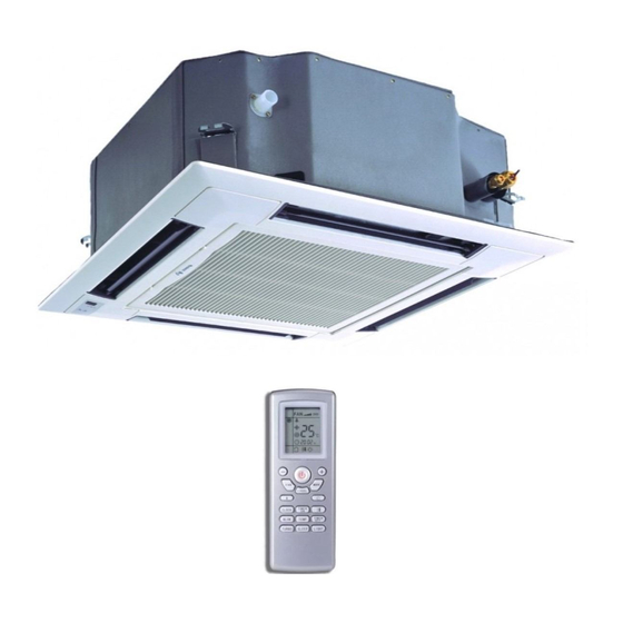
- Page 1 Service Manual AZI-CR35VB/I AZI-CR50VB/I AZI-CR70VB/I...
-
Page 2: Table Of Contents
Service Manual Table of Contents Part Ⅰ : Technical Information ...............1 1. Summary ........................1 2. Specification ......................2 2.1 Specification Sheet ......................2 3. Outline Dimension Diagram ................5 4. Refrigerant System Diagram ..............6 5. Electrical Part ......................7 5.1 Wiring Diagram .........................7 5.2 PCB Printed Diagram .......................9 6. -
Page 3: Part Ⅰ : Technical Information
Service Manual Part Ⅰ : Technical Information 1. Summary Indoor Unit AZI-CR35VB/I AZI-CR50VB/I AZI-CR70VB/I Remote Controller YT1F(MOTO) Technical Information... -
Page 4: Specification
Service Manual 2. Specification 2.1 Specification Shee Parameter Unit Value Model AZI-CR35VB/I AZI-CR50VB/I Product Code CN510N0120 CN510N0130 Rated Voltage 220-240 220-240 Power Rated Frequency Supply Phases Cooling Capacity 3.50 4.50 Heating Capacity 4.00 Air flow volume(SH/H/M/L/SL) 650/560/520/450/- 710/670/590/450/- Dehumidifying Volume... - Page 5 Service Manual Parameter Unit Value Model AZI-CR70VB/I Product Code CN510N0140 Rated Voltage 220-240 Power Rated Frequency Supply Phases Cooling Capacity 7.10 Heating Capacity Air flow volume(SH/H/M/L/SL) 1280/1220/1100/880/- Dehumidifying Volume Fan Type Centrifugal Fan Diameter-height Φ450-142 Fan Motor Cooling Speed(SH/H/M/L/SL) 650/620/560/450/- Fan Motor Heating Speed(SH/H/M/L/SL) 650/620/560/460/- Fan Motor Power Output...
- Page 6 Service Manual Note: Nominal capacities are based on the follow conditions. Mode Indoor Outdoor DB:27 (80.6) DB:35(95) Cooling WB:19 (66.2) WB:24(75.2) DB:20 (68) DB:7(44.6) Heating WB:--(--) WB:6 (42.8) Piping Length The air volume is measured at the relevant standard external static pressure. Noise is tested in the semianechoic room, so it should be slightly higher in the actual operation due to environmental change.
-
Page 7: Outline Dimension Diagram
Service Manual 3. Outline Dimension Diagram AZI-CR35VB/I AZI-CR50VB/I AZI-CR70VB/I Unit:mm Item Model AZI-CR35VB/I AZI-CR50VB/I AZI-CR70VB/I Technical Information... -
Page 8: Refrigerant System Diagram
Service Manual 4. Refrigerant System Diagram Technical Information... -
Page 9: Electrical Part
Service Manual 5. Electrical Part 5.1 Wiring Diagram ● Instruction Symbol Symbol Color Symbol Symbol Color Symbol Name White Green Jumper cap Yellow Brown COMP Compressor Blue Grounding wire YEGN Yellow/Green Black Violet Orange Note: Jumper cap is used to determine fan speed and the swing angle of horizontal lover for this model. ●... - Page 10 Service Manual 600007060124 These circuit diagrams are subject to change without notice, please refer to the one supplied with the unit. Technical Information...
-
Page 11: Pcb Printed Diagram
Service Manual 5.2 PCB Printed Diagram ˜ T op view Name Interface of fan Interface of live wire Fuse Interface of netural wire Air terminal Terminal with outdoor unit communication wire Water pump control Interface of ambient temperature sensor Interface of tube temperature sensor 10 Water full detection terminal Up&down swing motor 12 Jumper cap terminal... -
Page 12: Function And Control
Service Manual 6. Function and Control 6.1 Remote Controller Introduction Buttons on remote controller ON/OFF button MODE button +/- button FAN button I FEEL button button button button CLOCK button TIMER ON/TIMER OFF button X-FAN button Note: X-FAN is the same with BLOW TEMP button TURBO button SLEEP button... - Page 13 Service Manual MODE button Press this button to select your required operation mode. AUTO COOL HEAT After selecting auto mode, air conditioner will operate automatically according to ambient temperature. Set temperature can’t be adjusted and will not be displayed as well. Press " FAN" button can adjust fan speed. Press " "...
- Page 14 Service Manual button Press this button can select up&down swing angle. Fan blow angle can be selected circularly as below: no display (horizontal louvers stops at current position) When selecting " ", air conditioner is blowing fan automatically. Horizontal louver will automatically swing up & down at maximum angle.
- Page 15 Service Manual When selecting " " with remote controller, temperature indicator on indoor unit displays outdoor ambient temperature. Note: Outdoor temperature display is not available for some models. At that time, indoor unit receives " "signal, while it displays indoor set temperature. It’s defaulted to display set temperature when turning on the unit.There is no display in the remote controller.
-
Page 16: Brief Description Of Modes And Functions
Service Manual 6.2 Brief Description of Modes and Functions 1.Basic function of system (1)Cooling mode (1) Under this mode, fan and swing operates at setting status. Temperature setting range is 16~30 (2) During malfunction of outdoor unit or the unit is stopped because of protection, indoor unit keeps original operation status. (2)Drying mode (1) Under this mode, fan operates at low speed and swing operates at setting status. - Page 17 Service Manual (8)I feel control mode After controller received I feel control signal and ambient temperature sent by remote controller, controller will work according to the ambient temperature sent by remote controller. (9)Compulsory defrosting function (1) Start up compulsory defrosting function Under ON status, set heating mode with remote controller and adjust the temperature to 16 C.
- Page 18 Service Manual (17)Instructions to the Error Indicating Lamps on the Panel of the Cassette Type Unit. Receiver "88" Dispaly" Auto" Button Power Timer "Test" Button Indicating Lamp Indicating Lamp Power and ON/OFF Indicating Lamp: It goes red when the unit is powered on while it goes white when the unit is started. Timer Indicating Lamp: Timer indicator on indoor unit will be on when timer ON is set under off status and timer OFF is set under on status.
-
Page 19: Part Ⅱ : Installation And Maintenance
Service Manual Part Ⅱ : Installation and Maintenance 7. Notes for Installation and Maintenance Safety Precautions: 10. If the power cord or connection wire is not long enough, please get the specialized power cord or connection wire Important! from the manufacture or distributor. Prohibit prolong the wire by yourself. - Page 20 Service Manual Safety Precautions for Installing and Relocating the Unit: To ensure safety, please be mindful of the following precautions. Warnings 1. When installing or relocating the unit, be sure to keep the refrigerant circuit free from air or substances other than the specified refrigerant Any presence of air or other foreign substance in the refrigerant circuit will cause system pressure rise or compressor rupture, resulting in injury.
- Page 21 Service Manual Main Tools for Installation and Maintenance 1. Level meter, measuring tape 2. Screw driver 3. Impact drill, drill head, electric drill 4. Electroprobe 5. Universal meter 6. Torque wrench, open-end wrench, inner hexagon spanner 7. Electronic leakage detector 8.
-
Page 22: Installation
Service Manual 8. Installation 8.1 Installation Dimension Diagram Indoor Installation and Maintenance... -
Page 23: Installation Of Cassette Type
Service Manual 8.2 Installation of Cassette Type 8.2 Installation of Cassette Type 8.2.1. Before Installation After receiving the machine, please check for any transport damage. If finding any surface o internal damage, please immediately report to the transport company or equipment company in writing. After receiving the machine, please check the unit and Note: There will be large amount of greasy dirt accumulated on the fan, heat exchanger and water accessories in reference to the packing list. - Page 24 Service Manual 8.2.3. Installing the Suspension Bolts (2) Place the panel at the unit, and latch the hooks beside and opposite the swing flap moto . (1) Using the installation template, drill holes for bolts (four (3) Latch other two hooks. holes).
-
Page 25: Maintenance
Service Manual 9. Maintenance 9.1 Error Code List If cut-off of water level switch is detected for 8s successively once Full water Water level energized, the system will enter protection switch full water protection. In this case, switch off the unit and then switch it on to eliminate this malfunction. -
Page 26: Troubleshooting For Main Malfunction
Service Manual 9.2 Troubleshooting for Main Malfunction ●Indoor unit: 1. Malfunction of Temperature Sensor F1, F2 Main detection points: ● Is the wiring terminal between the temperature sensor and the controller loosened or poorly contacted? ● Is there short circuit due to trip-over of the parts? ●... - Page 27 Service Manual 2. Malfunction of Blocked Protection of IDU Fan Motor H6 Start Turn the fan blades by hand under power-off condition Adjust the motor and blade Whether the fan blades assembly so that rotor can run can run smoothly? smoothly.
- Page 28 Service Manual 3. Malfunction of Protection of Jumper Cap C5 Main detection points: ● Is there jumper cap on the mainboard? ● Is the jumper cap inserted correctly and tightly? ● The jumper is broken? ● The motor is broken? ●...
- Page 29 Service Manual 4. Communication malfunction E6 Start Cut off power supply. Check if connection line of IDU and ODU and the wire inside electric box are correctly connected. Connect the line Correct connection? according to Malfunction eliminated? wiring diagram. Main board matches Match correctly with display board? Main board of Malfunction eliminated?
- Page 30 Service Manual Troubleshooting for F0 malfunction Heat exchangers are Clean the heat exchangers and remove Malfunction is too dirty or the air inlet/outlet eliminated. blockage of air inlet/outlet. is blocked. Compressor doesn't work Malfunction is Make compressor run normally. normally. Strange noise or leakage occurs. eliminated.
- Page 31 Service Manual 6. Full Water Protection E9 Installation and Maintenance...
-
Page 32: Maintenance Method For Normal Malfunction
Service Manual 9.3 Maintenance Method for Normal Malfunction 1. Air Conditioner Can't be Started Up Possible Causes Discriminating Method (Air conditioner Status) Troubleshooting Confirm whether it's due to power failure. If yes, No power supply, or poor After energization, operation indicator isn’t bright wait for power recovery. - Page 33 Service Manual 4. ODU Fan Motor Can't Operate Possible causes Discriminating method (air conditioner status) Troubleshooting Connect wires according to wiring diagram to Wrong wire connection, or poor Check the wiring status according to circuit make sure all wiring terminals are connected connection diagram firmly...
-
Page 34: Removal Procedure
Service Manual 10. Removal Procedure Warning: Be sure to wait for a minimum of 20 minutes after turning off all power supplies and discharge the refrigerant completely before removal. 1. Loosen the screws fixing the water tray Use screwdriver to loosen the screws fixing the water tray 2. - Page 35 Service Manual 4. Remove the fan Remove the fan 5. Loosen the screws fixing the motor Use screwdriver to loosen the screws fixing the motor 6. Remove the motor and replace it Remove the motor and replace it 7. Tighten the screws fixing the motor Use screwdriver to tighten the screws fixing the motor.
- Page 36 Service Manual 8. Mount the fan and tighten the fixing bolts Mount the fan and use spanner to tighten the bolts fixing the fan. 9. Mount the water tray and tighten the screws Use screwdriver to loosen the screws fixing the water tray 10.Removal and Installation of Drainage Pump Loosen the screws...
- Page 37 Service Manual Take out the pump and replace it Connect the drainage pipe and use screwdriver to tighten the screws fixing the water pump. Mount the water tray and tighten the screws Use screwdriver to loosen the screws fixing the water tray Installation and Maintenance...
- Page 38 General representative of the Azuri air conditioners Split, Vukovarska 148 Zagreb, Zagrebačka avenija 104 Sarajevo, Pijačna 14K Tel: +385 (0)21 453 400 Tel: +385 (0)1 60 64 777 Tel: +387 (0)33 840 200 Fax: +385 (0)21 473 943 Fax: +385 (0)1 60 64 778 Fax: +387 (0)33 840 203 deltron@deltron.hr...
Need help?
Do you have a question about the AZI-CR35VB/I and is the answer not in the manual?
Questions and answers