Advertisement
Quick Links
Advertisement

Summary of Contents for American Flyer FasTrack S-Gauge
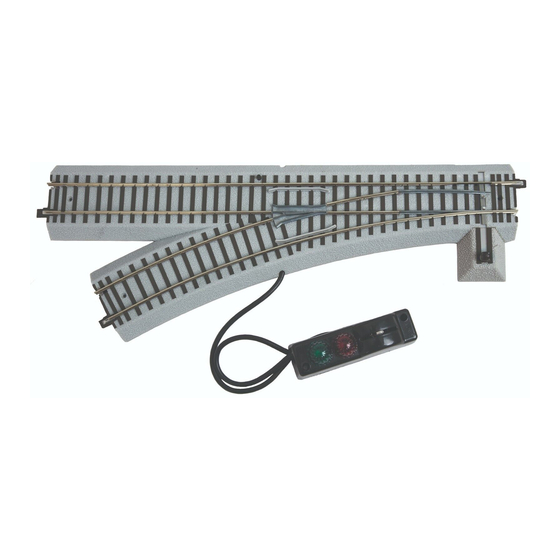
- Page 1 74-7941-250 5/15 RH / LH Remote Switch RH / LH Remote Switch Owner’s Manual Owner’s Manual...
- Page 2 You may choose to remove the installed manual controllers and forgo that wiring all together. The switch connects easily to other American Flyer FasTrack track sections. Use the switch to join two track loops, create a switching yard, or add a siding. Run your trains around your...
- Page 3 Joining the track sections asTrack track sections join together easily. With interlocking roadbed sections and metal rail joiners, the track fits together securely so you always have good electrical contact. Take a look at Figure 1 to see how to join the track sections. 1.
- Page 4 Operating the switch in conventional mode ou may operate the switch using the controller or the illuminated switch lamp on the roadbed. Once power is applied, the lamp will illuminate indicating that power is being applied to the track. Refer to Figure 2. To operate the switch using the controller, power up the track, then pull the lever to the opposite position.
- Page 5 Operating the switch in conventional mode continued Switch lamp Lamp & LED location Switch Figure 3. Re-inserting the lamp...
- Page 6 Changing the switch stand location ou may choose to position the switch stand either inside or outside the loop of track. Regardless of position, power will be supplied to the rails at all times. Follow these steps and refer to Figure 4 to change the location of the switch stand. 1.
- Page 7 Command Control operations Operating your switches in the Command Control environment our American Flyer switch is equipped with Command Control operation. To get your switch in action, set PowerMasters to CMD or set all power supplies on full (no more than 18 volts AC).
- Page 8 Command Control operations continued Programming your switches Soft Set Programming The TMCC switch incorperates “Soft Set Technology” which allows the operator to change the ID# (1-99) without physically activating the program button. This is great for switches that are not easily accessable. 1.
- Page 9 Routing the controller cable he controller cable has been routed through the notch on the curved side of the roadbed at the factory. You may choose to route the controller cable through the notch on the straight side of the roadbed. As illustrated in Figure’s 6A below and 6B on page 10, gently lift the controller cable from the notch.
- Page 10 Routing the controller cable continued screws screw RIGHT HAND SWITCH cable metal tabs Figure 6B. Rerouting the controller cable (Right Hand Switch) Removing the controller cable o remove the controller cable for wireless operation, use a flat head screwdriver to loosen the screws where the wires are attached to the switch.
- Page 11 Powering the switch through a separate power supply ou may choose to connect the switch to a separate power supply to operate the switch when track power is off or set to a low voltage. This is most beneficial to those operating in the conventional environment.
- Page 12 Lionel Limited Warranty Policy & Service his Lionel product, including all mechanical and electrical components, moving parts, motors and structural components, with the exception of LIGHT BULBS, LED’s & TRACTION TIRES are warranted to the original owner-purchaser for a period of one year from the original date of purchase against original defects in materials or workmanship when purchased through a Lionel Authorized Retailer*.
Need help?
Do you have a question about the FasTrack S-Gauge and is the answer not in the manual?
Questions and answers
My new s gauge Lionel train will not react to remote. Switch under engine is on remote. Red light on track just blinks. Does not stay on
The red light on the track blinking and not staying on could indicate that the switch is in programming mode or has not been properly assigned an ID. If the switch is not responding to the remote, it may not be correctly programmed with a unique switch ID, or there could be an issue with the power supply (it requires 14 Volts AC to operate). Ensure that the switch has been programmed correctly by following the reprogramming steps:
1. Press the SET button—this will cause the lantern to flicker and then blink for about 5 seconds.
2. When the blinking stops, press SW and enter the new switch ID number.
3. Alternate AUX1 and AUX2 to verify reprogramming.
If multiple command switches are installed, verify that each has a unique switch ID to avoid interference. Also, check that the power connections are secure and that the switch is receiving the required voltage.
This answer is automatically generated
How to isolate one side of a manual switch so the power is supplied to the track depending on which way the switch is set.