Table of Contents
Advertisement
Quick Links
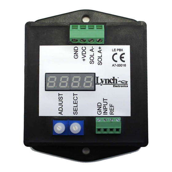
Digital Display Proportional Valve Driver
LE PB X
Potted Enclosure
Features and Benefits
►
Microcontroller design.
►
Independent adjustments (Incl. ramp up & ramp down).
►4 digit extra bright seven segment LED display.
►
Large, easy-to-use adjustments and readout.
►
Display and adjust actual values (Current & Voltage).
Wide range of supply voltage.
►
User selectable input type through menu setup.
►
►
Wide ramp time range (0 to 99.5 Sec).
Rugged design offers vibration resistance.
►
Direct mounting.
►
►Housed in fire retardant two part epoxy resin (UL94-VO).
►
Simple control with analog input, locally supplied reference voltage.
►Energy efficient PWM circuit/no heat sink required.
►Electronic limiting circuit/short circuit proof.
►Reverse polarity, command Input protection.
►Load can be connected & disconnected live.
Current sensing maintains output regardless of changes in supply voltage and coil resistance.
►
►
Easy troubleshooting/cable length not an issue.
LE PB X Standard Specifications
Operating voltage:
Maximum output current:
Input signal:
Maximum ramp time:
PWM / Dither frequency:
Linearity:
Operating Temperature:
PART NUMBER SYSTEM
TYPE
MODEL
Lynch Electronics
• Proportional Solenoid Driver
Contact Us For More Information
Toll Free
Tel: 1 (888) 626-4365 Tel: +1 (905) 363-2400
Fax: 1 (800) 263-5807
WE RESERVE THE RIGHT TO DISCONTINUE MODELS, OR CHANGE SPECIFICATIONS WITHOUT NOTICE OR INCURRING OBLIGATION
voe
9 to 36
3.00Amps
5V, 1 0V, 4 to 20mA
99.5 Sec
40-450Hz
1%
°
°
-40
to +80
Celsius
Proportional Solenoid Driver, Single, Potted Enclosure.
FORM
; Single, Potted Enclosure, Screw Mounted
Local & International
Canada
1799 Argentia Road
Fax: +1 (905) 363-1191
Mississauga, Ontario L5N 3A2
,-, ,-, ,-, ,-,
Ct Ct Ct Ct
Several Forms Available
Note: Customization of functionality and enclosure type are available on request.
-----------------
Example: LE PBX
•
' I
RAMP TIME
USA
3790 Commerce Court,
Suite 500, North Tonawanda sales@lynch.ca
New York, 14120
Electronics
A Division of Lynch Fluid Controls
PAR AME TE RS = X
0 to 5V, 0 to 10V, 4 to 20mA,
•
•
0.20 to 3.00A
0 to 99.5 Sec
Online
www.Lynch.ca
CE�
LE PB X-0218
Advertisement
Table of Contents

Summary of Contents for Lynch Electronics LE PB X
- Page 1 ►Load can be connected & disconnected live. Current sensing maintains output regardless of changes in supply voltage and coil resistance. ► ► Easy troubleshooting/cable length not an issue. LE PB X Standard Specifications Several Forms Available Operating voltage: 9 to 36 Maximum output current: 3.00Amps...
- Page 2 � ...I �+�� I s . s . 1 s . s . � � � � Contact Us For More Information LE PB X-1017 Local & International Online Toll Free Canada Tel: +1 (905) 363-2400 1799 Argentia Road 3790 Commerce Court, www.Lynch.ca...
- Page 3 LE PBX Electronics SCHEMATICS A Division of Lynch Fluid Controls EXTERNAL INPUT SIGNAL CONNECTION " " " set to " =-� FUSE GND 9 TO 36VDC W0TO10VDC POWER SUPPLY ANALOGUE OUTPUT ------����r:i_D CHANNEL SIGNAL L--- POTENTIOMETER CONNECTION " " "...
- Page 4 Emission: EN 61000-6-4: 2007, EN 55011:2009 Immunity: EN 61000-6-2: 2005, EN 61000-4-2, EN 61000-4-3, EN 61000-4-4, EN 61000-4-6, EN 61000-4-8:2001 RoHS: EN 50581:2012 Contact Us For More Information LE PB X-1017 Local & International Online Toll Free Canada Tel: +1 (905) 363-2400...
- Page 5 --- - - - - - - - - - - - - - � time [milliseconds] command signal [Volts or mA] Contact Us For More Information LE PB X-0718 Local & International Canada Onlin e Toll Fre e Tel: +1 (905) 363-2400...
- Page 6 LE PBX Electronics SET-UP PROCEDURE (NOTE: Prior to setting up parameters, you must select proper Input Signal setting for your system) Available Input Signal options (0 to 10V) <=Default (0 to 5V) (4 to 20mA) ***Applying improper Input Signal to wrong setting on the Driver may be damaging to Driver Unit and may cause driver to fault to Error Status mode*** SET-UP 1.
Need help?
Do you have a question about the LE PB X and is the answer not in the manual?
Questions and answers