Table of Contents
Advertisement
Quick Links
Advertisement
Chapters
Table of Contents

Related Manuals for AERMEC VES Series


Summary of Contents for AERMEC VES Series
- Page 1 VES030 VES130 VES230 VES330 VES040 VES140 VES240 VES340 IVES0LJ 1707 - 5880761_01...
-
Page 2: Osservazioni
OSSERVAZIONI REMARKS REMARQUES HINWEISE OBSERVACIONES... -
Page 3: Table Of Contents
TABLE OF CONTENTS osservazioni ....................2 remarks ......................2 remarques ....................2 hinweise .......................2 observaciones....................2 important information and maintenance ........5 packaging ....................5 use ........................5 description of the unit ................6 system examples ..................6 main components ...................7 description of the components ............7 selection criteria .................. - Page 4 TRASPORTO • TRANSPORT • TRANSPORT • TRANSPORT • TRANSPORTE NICHT nass machen. NON bagnare. Tenere al KEEP DRY. Keep out of NE PAS mouiller. Tenir à NO mojar. Conservar Vor Regen geschützt riparo dalla pioggia. the rain. l’abri de la pluie. protegido de la lluvia.
-
Page 5: Important Information And Maintenance
IMPORTANT INFORMATION AND MAINTENANCE DO NOT USE WATER THAT IS TOO HOT During operation, noise and/or a creaking AT T E N T I ON : t h e f a n co i l is Clean the fan coil by using soft cloths or sound may be heard from inside the connected to the power supply and device due to the heat expansion of the... -
Page 6: Description Of The Unit
DESCRIPTION OF THE UNIT PURPOSE OF THE VES FAN COILS The fan coil is a terminal used to treat air, both during winter and summer. The VES fan coils have been designed to meet any requirement in ducted systems. In particular, the fact that the unit can be integrated in the VMF system allows you to control the individual fan coil with accessories up to the management of the VES inserted in complex networks of fan coils and relative accessories. -
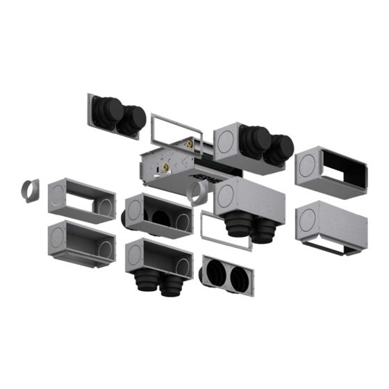
Page 7: Main Components
MAIN COMPONENTS VES 030 VES 040 VES 130 VES 140 VES 230 VES 240 VES 330 14 15 VES 340 1 Air delivery 8 Water drain on the coil 15 Connection box of the electric motor 2 Frame (support structure) 9 Condensate drain 16 Centrifugal fan 3 Air vents on the coil... -
Page 8: Selection Criteria
SELECTION CRITERIA The VES wall-ceiling mounted fan coils are The sensitive and total cooling yields at For the ducted installations the sound suitable for both vertical and horizontal maximum speed depending on the power level is expressed in terms of ducted installations. - Page 9 OPERATING LIMITS Maximum water inlet temperature °C Maximum water inlet temperature recommended °C Maximum operating pressure Minimum water flow rate (Main coil) Maximum water flow rate (Main coil) 1000 1000 1000 1000 1000 1000 1500 1500 Minimum water flow rate (Heating Only Coil) Maximum water flow rate (Heating Only Coil) Environment temperature limits (Ta) °C...
- Page 10 TECHNICAL DATA mod. 2-pipe system con guration 3688 3916 6289 6575 7160 7909 10507 10951 thermal power (70°C) 3374 3568 5833 6089 6500 7141 9343 10017 1820 2366 4397 4518 5350 5800 7813 8312 water ow rate pressure drops 2224 2362 3793 3966...
- Page 11 mod. 2-pipe system con guration type fans fans useful static pressure input power maximum input current 0.37 0.37 0.41 0.41 0.58 0.58 0.66 0.66 db(a) sound power (inlet+radiator) db(a) db(a) db(a) sound power (outlet) db(a) db(a) coil connections 3/4" 3/4" 3/4"...
- Page 12 COOLING POWER YIELDED The table shows the sensitive and total cooling capacities at table by the corrective factors indicated for each speed. NB: The yield values marked in bold indicate the nominal maximum speed depending on the temperature of the water entering, of its heat drop and temperature of the air with dry value.
-
Page 13: Cooling Capacity Output Ves30
COOLING CAPACITY OUTPUT VES30 VES 30 Tw(in) = 5°C Tw(in) = 7°C Tw(in) = 9°C Tw(in) = 11°C Tw(in) = 13°C Dt w [°C] [°C] [°C] 1509 1139 1206 1141 1500 1284 1199 1129 1494 1427 1195 1273 1066 1066 1472 1472 1337... -
Page 14: Cooling Capacity Output - Ves40
COOLING CAPACITY OUTPUT - VES40 VES 40 Tw(in) = 5°C Tw(in) = 7°C Tw(in) = 9°C Tw(in) = 11°C Tw(in) = 13°C Dt w [°C] [°C] [°C] 2166 1223 1731 1057 1251 1225 2153 1379 1720 1212 1335 1074 1132 2144 1532 1715... -
Page 15: Cooling Capacity Output - Ves130
COOLING CAPACITY OUTPUT - VES130 VES 130 Tw(in) = 5°C Tw(in) = 7°C Tw(in) = 9°C Tw(in) = 11°C Tw(in) = 13°C Dt w [°C] [°C] [°C] 2456 1962 1962 1695 1418 1966 1057 1057 2441 2211 1950 1945 1514 1514 1284 1284... -
Page 16: Cooling Capacity Output - Ves140
COOLING CAPACITY OUTPUT - VES140 VES 140 Tw(in) = 5°C Tw(in) = 7°C Tw(in) = 9°C Tw(in) = 11°C Tw(in) = 13°C Dt w [°C] [°C] [°C] 2605 1994 2081 1723 1504 1998 1121 1121 2589 2247 2069 1976 1605 1605 1362 1362... -
Page 17: Cooling Capacity Output - Ves230
COOLING CAPACITY OUTPUT - VES230 VES 230 Tw(in) = 5°C Tw(in) = 7°C Tw(in) = 9°C Tw(in) = 11°C Tw(in) = 13°C Dt w [°C] [°C] [°C] 3108 2426 2483 2096 1795 2431 1338 1338 1040 1040 3089 2734 2468 2405 1915 1915... -
Page 18: Cooling Capacity Output - Ves240
COOLING CAPACITY OUTPUT - VES240 VES 230 Tw(in) = 5°C Tw(in) = 7°C Tw(in) = 9°C Tw(in) = 11°C Tw(in) = 13°C Dt w [°C] [°C] [°C] 3212 2606 2567 2252 1855 2611 1383 1383 1075 1075 3193 2937 2551 2583 1980 1980... -
Page 19: Cooling Capacity Output - Ves330
COOLING CAPACITY OUTPUT - VES330 VES 330 Tw(in) = 5°C Tw(in) = 7°C Tw(in) = 9°C Tw(in) = 11°C Tw(in) = 13°C Dt w [°C] [°C] [°C] 4225 3233 3376 2794 2440 3240 1819 1819 1413 1413 4199 3645 3355 3205 2604 2604... -
Page 20: Cooling Capacity Output - Ves340
COOLING CAPACITY OUTPUT - VES340 VES 330 Tw(in) = 5°C Tw(in) = 7°C Tw(in) = 9°C Tw(in) = 11°C Tw(in) = 13°C Dt w [°C] [°C] [°C] 4494 3429 3591 2963 2595 3435 1935 1935 1504 1504 4467 3865 3569 3399 2770 2770... -
Page 21: Heating Capacity Output - 2-Pipe System Configuration
HEATING CAPACITY OUTPUT - 2-PIPE SYSTEM CONFIGURATION VES30 VES40 T.w. Water T.w. Water Air R.T. in [°C] Air R.T. in [°C] [°C] [°C] BTU/h BTU/h BTU/h BTU/h BTU/h BTU/h W BTU/h BTU/h W BTU/h W BTU/h 4136 14111 3957 13500 3780 12898 3606 12306 3435 11722 4391 14983 4201 14335 4014 13696 3829 13066 3648 12446 10 4041 13788 4683 15979 3688 12584 3514 11991 3341 11398 10 4291 14640 4973 16967 3916 13362 3732 12732 3547 12103... -
Page 22: Heating Capacity Output - 4-Pipe System Configuration
VES330 VES340 T.w. Water T.w. Water Air R.T. in [°C] Air R.T. in [°C] [°C] [°C] BTU/h BTU/h BTU/h BTU/h BTU/h BTU/h BTU/h BTU/h BTU/h BTU/h 5 11782 40202 11272 38462 10769 36747 10275 35058 9787 33395 5 12280 41900 11748 40087 11225 38300 10709 36540 10201 34806 10 11512 39280 13342 45524 10507 35851 10012 34162 9517 32474 10 11998 40940 13906 47448 10951 37366 10435 35606 9919 33846 15 11197 38206 10687 36466 10185 34751 9682 33036 9195 31373... -
Page 23: Main Coil Pressure Drops When Cold With Water 7/12°C
MAIN COIL PRESSURE DROPS WHEN COLD WITH WATER 7/12°C VES 230 VES 30 VES 240 VES 130 VES 340 VES 40 VES 330 VES 140 1000 1200 1400 1600 1800 Water flow rate [l/h] MAIN COIL PRESSURE DROPS WHEN COLD WITH WATER 13/18°C VES 230 VES 30 VES 240... -
Page 24: Main Coil Pressure Drops When Hot With Water 50/45°C
MAIN COIL PRESSURE DROPS WHEN HOT WITH WATER 50/45°C VES 230 VES 240 VES 340 VES 30 VES 130 VES 140 VES 330 VES 40 1000 1200 1400 1600 1800 2000 Water flow rate [l/h] MAIN COIL PRESSURE DROPS WHEN HOT WITH WATER 70/60°C Water flow rate [l/h] Average water temperature °C... -
Page 25: Flow Static Pressure
FLOW STATIC PRESSURE The fan coils of the VES series have been designed to adjust the static pressure provided by the fan according to the duct pressure drops, by selecting an appropriate speed. The chart shows the useful static pressure of the machines with an enhanced multi-speed motor according to the fan air flow rate and speed (V1...V6). - Page 26 FLOW STATIC PRESSURE The fan coils of the VES series have been designed to adjust the static pressure provided by the fan according to the duct pressure drops, by selecting an appropriate speed. The chart shows the useful static pressure of the machines with an enhanced multi-speed motor according to the fan air flow rate and speed (V1...V6).
- Page 27 FLOW STATIC PRESSURE The fan coils of the VES series have been designed to adjust the static pressure provided by the fan according to the duct pressure drops, by selecting an appropriate speed. The chart shows the useful static pressure of the machines with an enhanced multi-speed motor according to the fan air flow rate and speed (V1...V6).
- Page 28 FLOW STATIC PRESSURE The fan coils of the VES series have been designed to adjust the static pressure provided by the fan according to the duct pressure drops, by selecting an appropriate speed. The chart shows the useful static pressure of the machines with an enhanced multi-speed motor according to the fan air flow rate and speed (V1...V6).
-
Page 29: Correction Factors In Functioning With Glycol Water
C O R R E C T I O N F A C T O R S F U N C T I O N I N G W I T H G LY C O L W A T E R Key: Pressure drops Flow rate... -
Page 30: Sound Power Level Expressed In Db A Ves 030-40
SOUND POWER LEVEL expressed in dB A VES 030-40 Maximum Medium Minimum Frequency Tot. Tot. Tot. dB[A] dB[A] dB[A] dB[A] dB[A] dB[A] dB[A] dB[A] dB[A] 39.4 35.6 37.0 37.1 33.2 34.9 28.4 24.8 26.0 38.0 36.2 33.2 35.8 34.0 31.1 27.4 25.8 22.4... -
Page 31: Sound Pressure Level Expressed In Db A Ves 130 - 140
SOUND POWER LEVEL expressed in dB A VES 130-140 Maximum Medium Minimum Frequency Tot. Tot. Tot. dB[A] dB[A] dB[A] dB[A] dB[A] dB[A] dB[A] dB[A] dB[A] 39.8 36.6 37.0 37.5 34.2 34.8 30.9 27.8 28.0 38.7 37.2 33.2 36.5 35.0 31.0 30.1 28.8 24.4... -
Page 32: Sound Power Level Expressed In Db A Ves 230-240
SOUND POWER LEVEL expressed in dB A VES 230-240 Maximum Medium Minimum Frequency Tot. Tot. Tot. dB[A] dB[A] dB[A] dB[A] dB[A] dB[A] dB[A] dB[A] dB[A] 41.8 38.6 39.0 38.5 35.2 35.8 32.9 29.8 30.0 40.7 39.2 35.2 37.5 36.0 32.0 32.1 30.8 26.4... -
Page 33: Sound Pressure Level Expressed In Db A Ves 330 - 340
SOUND POWER LEVEL EXPRESSED IN DB A VES 330-340 Maximum Medium Minimum Frequency Tot. Tot. Tot. dB[A] dB[A] dB[A] dB[A] dB[A] dB[A] dB[A] dB[A] dB[A] 43.4 39.6 41.0 40.1 36.2 37.8 22.4 18.8 20.0 42.0 40.2 37.2 38.8 37.0 34.0 21.4 19.8 16.4... -
Page 34: Accessories
ACCESSORIES els not supplied by Aermec The flow rate of the project is crucial to refine the a range of dedicated wall-mounted controls is available selection of the valves shown in the compatibility but it is essential to choose between these panels for simple... - Page 35 2-way valve kit • • • • • • • • VCFD3/324 3-way valve kit For heating only coil • • • • VCF45/4524 2-way valve kit For heating only coil VCFD4/424 • • • • Cold side control and balancing combined valve * VJP060/060M •...
- Page 36 ACCESSORIES MANDATORY ACCESSORIES FOR OPERATION: • VMF-SIT3: VMF System thermostat • SIT3: Thermostat inter face board. • SIT5: Thermostat inter face board. interface board. Mandatory accessory on Mandator y accessory on VES units Accessory mandatory on VES units with VES units supplied with VMF-E0 or VMF- coupled to thermostats different to the up to 2 water valves, combined with E1 thermostat.
- Page 37 ACCESSORIES VMF - VARIABLE MULTI FLOW SYSTEM • VMF: Variable Multi Flow System • In addition to the centralised control Hydronic system management and provided by the VMF-E5 panel, the control unit for air conditioning, heating MASTER fan coils must be equipped 3) Control of a network consisting and domestic hot water production.
- Page 38 ACCESSORIES VMF E1 ELECTRONIC THERMOSTAT FOR FAN COILS to fan coils; it requires an interface on the Every thermostat applied to a VES wall (VMF-E4). series unit must feature a VMF-SIT3 The VMF-E1 thermostat must be applied to board. the side of the fan coil. The VMF-E1 accessor y is an evolved electronic thermostat kit to be applied VMF-E1 consists of:...
- Page 39 ACCESSORIES VMF E4 CONTROL PANEL FOR VMF SERIES THERMOSTATS, WALL-MOUNTED INSTALLATION Flush electronic control panel for wall-mounted installation, VMF E4 advanced interface for VMF series thermostats. It must be coupled with VMF-E0 or VMF-E1 thermostats. Digital display, "Touch" keyboard, often only 11mm can be installed on wall on 503 Type recessed electric boxes and compatible with 502 Type, M20 boxes (see installation manual).
- Page 40 ACCESSORIES VMF-E5B / VMF-E5N MAIN INTERFACE FOR SYSTEM SUPERVISION ATTENTION: The VMF-E5 panel allows you to manage individual masters. VMF-E5B The slave units connected to each master cannot be managed VMF-E5N individually by the VMF-E5 panel, but they take on the settings of the master to which they are connected.
- Page 41 ACCESSORIES CONTROL PANELS AND THERMOSTATS - MANDATORY ACCESSORIES FOR OPERATION: The complete features of the control Some control panels require coupling with panels are described in the dedicated other accessories, consult the relative sheet. For further information, refer to documentation. the accessory instructions.
- Page 42 ACCESSORIES DUCTING ACCESSORIES: RDA_V STRAIGHT INTAKE FITTING Straight intake fitting with rectangular flange for ducting. Made of galvanised sheet steel. It can house the air filter. DIMENSIONS Mod. RDA450V 1053 RDA670V 1453 RPA_V INTAKE PLENUM WITH RECTANGULAR FLANGE RPA_V is an intake plenum with rectangular flange made of galvanised sheet steel.
- Page 43 ACCESSORIES DUCTING ACCESSORIES: RPM_V FLOW PLENUM WITH RECTANGULAR FLANGE RPM_V is a flow plenum with rectangular flange made of galvanised sheet steel and fully insulated. This accessory is for connection of a channel with a rectangular section to the flow vent of the VES unit.
- Page 44 ACCESSORIES WATER VALVES FOR MAIN COIL • VCF45C: Kit made up of 3-way motorised valves with insulating shell, insulated copper fittings and pipes. For the main coil. Power supply 230V-1-50Hz . • VCF47C: Kit made up of 3-way motorised valves with insulating shell, insulated copper fittings and pipes.
-
Page 45: Information Regarding Installation
INFORMATION REGARDING INSTALLATION The fan coil must be installed in a position installed in two positions: ATTENTION: make sure that the that allows the air to be distributed - in its seat in the coil; power supply has been disconnected throughout the room and there are no - on the flow pipe upstream of the valve. - Page 46 HYDRAULIC CONNECTIONS - Make the hydraulic connections. ATTENTION: Always use a wrench and counter-wrench to fix the pipes. The position, type and diameter of the hydraulic connections are specified in the dimensional data. It is recommended to insulate water pipes and/or to install the suitable auxiliary condensate collection tray, available as an accessory, in order to avoid dripping...
-
Page 47: Coil Rotation
CONDENSATE DRAIN The fan coil tray has 2 condensate drains prevents odours from returning into the on the right and left side. environment. We recommend using the condensate Run an operating and condensate drain drain fitting on the side of the hydraulic system seal test by pouring water in the connections. -
Page 48: Dimensions [Mm]
DIMENSIONS [mm] Slot 20x9 Ø17,5 1027 1027 1148 1148 1001 1001 1122 1122 1072 1072 1102 1102 Weight 29.5 32.5 IVES0LJ 1707 - 5880761_01... - Page 49 The relevant products are featured on the website www.eurovent-certification.com The technical data given on this documentation is not binding. AERMEC S.p.A. reserves the right to apply all the modifications deemed necessary for improving the product at any time. AERMEC S.p.A.
- Page 50 VES_I030 VES_I130 VES_I230 VES_I330 VES_I040 VES_I140 VES_I240 VES_I340 5880751_01 17.07...
- Page 51 OSSERVAZIONI REMARKS REMARQUES HINWEISE OBSERVACIONES...
- Page 52 SUMMARY REMARKS .....................2 IMPORTANT INFORMATION AND MAINTENANCE ......5 PACKAGING ....................5 USE .........................5 DESCRIPTION OF THE UNIT ..............6 SYSTEM EXAMPLES ..................6 MAIN COMPONENTS ................7 DESCRIPTION OF THE COMPONENTS ..........7 SELECTION CRITERIA ................8 OPERATING ENVIRONMENT ..............8 COOLING CAPACITY OUTPUT VES_I30 ...........13 COOLING CAPACITY OUTPUT - VES_I40 .........14 COOLING CAPACITY OUTPUT - VES_I130 ........15...
- Page 53 TRASPORTO • TRANSPORT • TRANSPORT • TRANSPORT • TRANSPORTE NICHT nass machen. NON bagnare. Tenere al KEEP DRY. Keep out of NE PAS mouiller. Tenir à NO mojar. Conservar Vor Regen geschützt riparo dalla pioggia. the rain. l’abri de la pluie. protegido de la lluvia.
-
Page 54: Important Information And Maintenance
IMPORTANT INFORMATION AND MAINTENANCE DO NOT USE WATER THAT IS TOO HOT During operation, noise and/or a creaking AT T E N T I ON : t h e f a n co i l is Clean the fan coil by using soft cloths or sound may be heard from inside the connected to the power supply and device due to the heat expansion of the... -
Page 55: Description Of The Unit
DESCRIPTION OF THE UNIT PURPOSE OF THE VES_I FAN COILS The fan coil is a terminal used to treat air, both during winter and summer. The VES_I fan coils have been designed to meet any requirement in ducted systems. In particular, the fact that the unit can be integrated in the VMF system allows you to control the individual fan coil with accessories up to the management of the VES_I inserted in complex networks of fan coils and relative accessories. -
Page 56: Main Components
MAIN COMPONENTS VES_I 030 VES_I 040 VES_I 130 VES_I 140 VES_I 230 VES_I 240 VES_I 330 14 15 VES_I 340 1 Air delivery 8 Water drain on the coil 15 Connection box of the electric motor 2 Frame (support structure) 9 Condensate drain 16 Centrifugal fan 3 Air vents on the coil... -
Page 57: Selection Criteria
SELECTION CRITERIA The VES_I wall-ceiling mounted fan The sensitive and total cooling yields at For the ducted installations the sound coils are suitable for both vertical and maximum speed depending on the power level is expressed in terms of horizontal ducted installations. temperature of the water entering, of air flow rate and static pressure and is its heat drop and temperature of the air... - Page 58 OPERATING LIMITS Maximum water inlet temperature °C Maximum water inlet temperature recommended °C Maximum operating pressure Minimum water flow rate (Main coil) Maximum water flow rate (Main coil) 1000 1000 1000 1000 1000 1000 1500 1500 Minimum water flow rate (Heating Only Coil) Maximum water flow rate (Heating Only Coil) Environment temperature limits (Ta) °C...
- Page 59 TECHNICAL DATA 5880751_01...
- Page 60 DIMENSIONAL DATA mm VES_I 1001 1001 1122 1122 1027 1027 1148 1148 Net weight 5880751_01...
- Page 61 COOLING POWER YIELDED The table shows the sensitive and total cooling capacities at table by the corrective factors indicated for each speed. NB: The yield values marked in bold indicate the nominal maximum speed depending on the temperature of the water entering, of its heat drop and temperature of the air with dry value.
-
Page 62: Cooling Capacity Output Ves_I30
COOLING CAPACITY OUTPUT VES_I30 VES_I30 Tw(in) = 5°C Tw(in) = 7°C Tw(in) = 9°C Tw(in) = 11°C Tw(in) = 13°C Dt w [°C] [°C] [°C] 1509 1139 1206 1141 1500 1284 1199 1129 1494 1427 1195 1273 1066 1066 1472 1472 1337 1438... -
Page 63: Cooling Capacity Output - Ves_I40
COOLING CAPACITY OUTPUT - VES_I40 VES_I40 Tw(in) = 5°C Tw(in) = 7°C Tw(in) = 9°C Tw(in) = 11°C Tw(in) = 13°C Dt w [°C] [°C] [°C] 2166 1223 1731 1057 1251 1225 2153 1379 1720 1212 1335 1074 1132 2144 1532 1715 1367... -
Page 64: Cooling Capacity Output - Ves_I130
COOLING CAPACITY OUTPUT - VES_I130 VES_I130 Tw(in) = 5°C Tw(in) = 7°C Tw(in) = 9°C Tw(in) = 11°C Tw(in) = 13°C Dt w [°C] [°C] [°C] 2456 1962 1962 1695 1418 1966 1057 1057 2441 2211 1950 1945 1514 1514 1284 1284 1053... -
Page 65: Cooling Capacity Output - Ves_I140
COOLING CAPACITY OUTPUT - VES_I140 VES_I140 Tw(in) = 5°C Tw(in) = 7°C Tw(in) = 9°C Tw(in) = 11°C Tw(in) = 13°C Dt w [°C] [°C] [°C] 2605 1994 2081 1723 1504 1998 1121 1121 2589 2247 2069 1976 1605 1605 1362 1362 1117... -
Page 66: Cooling Capacity Output - Ves_I230
COOLING CAPACITY OUTPUT - VES_I230 VES_I230 Tw(in) = 5°C Tw(in) = 7°C Tw(in) = 9°C Tw(in) = 11°C Tw(in) = 13°C Dt w [°C] [°C] [°C] 3108 2426 2483 2096 1795 2431 1338 1338 1040 1040 3089 2734 2468 2405 1915 1915 1625... -
Page 67: Cooling Capacity Output - Ves_I240
COOLING CAPACITY OUTPUT - VES_I240 VES_I230 Tw(in) = 5°C Tw(in) = 7°C Tw(in) = 9°C Tw(in) = 11°C Tw(in) = 13°C Dt w [°C] [°C] [°C] 3212 2606 2567 2252 1855 2611 1383 1383 1075 1075 3193 2937 2551 2583 1980 1980 1679... -
Page 68: Cooling Capacity Output - Ves_I330
COOLING CAPACITY OUTPUT - VES_I330 VES_I330 Tw(in) = 5°C Tw(in) = 7°C Tw(in) = 9°C Tw(in) = 11°C Tw(in) = 13°C Dt w [°C] [°C] [°C] 4225 3233 3376 2794 2440 3240 1819 1819 1413 1413 4199 3645 3355 3205 2604 2604 2209... -
Page 69: Cooling Capacity Output - Ves_I340
COOLING CAPACITY OUTPUT - VES_I340 VES_I330 Tw(in) = 5°C Tw(in) = 7°C Tw(in) = 9°C Tw(in) = 11°C Tw(in) = 13°C Dt w [°C] [°C] [°C] 4494 3429 3591 2963 2595 3435 1935 1935 1504 1504 4467 3865 3569 3399 2770 2770 2350... -
Page 70: Heating Capacity Output - 2-Pipe System
HEATING CAPACITY OUTPUT - 2-PIPE SYSTEM CONFIGURATION VES_I30 VES_I40 T.w. Water T.w. Water Air R.T. in [°C] Air R.T. in [°C] [°C] [°C] BTU/h BTU/h BTU/h BTU/h BTU/h BTU/h W BTU/h BTU/h BTU/h BTU/h 4136 14111 3957 13500 3780 12898 3606 12306 3435 11722 4391 14983 4201 14335 4014 13696 3829 13066 3648 12446 10 4041 13788 4683 15979 3688 12584 3514 11991 3341 11398 10 4291 14640 4973 16967 3916 13362 3732 12732 3547 12103... - Page 71 VES_I330 VES_I340 T.w. Water T.w. Water Air R.T. in [°C] Air R.T. in [°C] [°C] [°C] BTU/h BTU/h BTU/h BTU/h BTU/h BTU/h BTU/h BTU/h BTU/h BTU/h 5 11782 40202 11272 38462 10769 36747 10275 35058 9787 33395 5 12280 41900 11748 40087 11225 38300 10709 36540 10201 34806 10 11512 39280 13342 45524 35851 10012 34162 9517 32474 10 11998 40940 13906 47448 10951 37366 10435 35606 9919 33846...
-
Page 72: Main Coil Pressure Drops When Cold With Water 7/12°C
MAIN COIL PRESSURE DROPS WHEN COLD WITH WATER 7/12°C VES_I 230 VES_I 30 VES_I 240 VES_I 130 VES_I 340 VES_I 40 VES_I 330 VES_I 140 1000 1200 1400 1600 1800 Water flow rate [l/h] MAIN COIL PRESSURE DROPS WHEN COLD WITH WATER 13/18°C VES_I 230 VES_I 30 VES_I 240... -
Page 73: Main Coil Pressure Drops When Hot With Water 65/55°C
MAIN COIL PRESSURE DROPS WHEN HOT WITH WATER 65/55°C VES_I1 30+BV130 VES_I33 0+BV162 VES_I2 30+BV230 VES_I 30+BV030 Water flow rate [l/h] MAIN COIL PRESSURE DROPS WHEN HOT WITH WATER 70/60°C Water flow rate [l/h] Average water temperature °C Multiplicative coefficients 1.03 0.96 0.91... -
Page 74: Flow Static Pressure
FLOW STATIC PRESSURE The fan coils of the VES_I series have been designed to adjust the static pressure provided by the fan according to the duct pressure drops, by selecting an appropriate speed. The chart shows the useful static pressure of the machines with an enhanced multi-speed motor according to the fan air flow rate and speed (V1...V6). -
Page 75: Correction Factors In Functioning
C O R R E C T I O N F A C T O R S F U N C T I O N I N G W I T H G LY C O L W A T E R Key: Pressure drops Flow rate... - Page 76 SOUND POWER LEVEL expressed in dB A VES_I 030-40 Maximum Medium Minimum Frequency Tot. Tot. Tot. dB[A] dB[A] dB[A] dB[A] dB[A] dB[A] dB[A] dB[A] dB[A] 39.4 35.6 37.0 37.1 33.2 34.9 28.4 24.8 26.0 38.0 36.2 33.2 35.8 34.0 31.1 27.4 25.8 22.4...
- Page 77 SOUND POWER LEVEL expressed in dB A VES_I 130-140 Maximum Medium Minimum Frequency Tot. Tot. Tot. dB[A] dB[A] dB[A] dB[A] dB[A] dB[A] dB[A] dB[A] dB[A] 39.8 36.6 37.0 37.5 34.2 34.8 30.9 27.8 28.0 38.7 37.2 33.2 36.5 35.0 31.0 30.1 28.8 24.4...
- Page 78 SOUND POWER LEVEL expressed in dB A VES_I 230-240 Maximum Medium Minimum Frequency Tot. Tot. Tot. dB[A] dB[A] dB[A] dB[A] dB[A] dB[A] dB[A] dB[A] dB[A] 41.8 38.6 39.0 38.5 35.2 35.8 32.9 29.8 30.0 40.7 39.2 35.2 37.5 36.0 32.0 32.1 30.8 26.4...
-
Page 79: Sound Power Level Expressed In Db A
SOUND POWER LEVEL EXPRESSED IN DB A VES_I 330-340 Maximum Medium Minimum Frequency Tot. Tot. Tot. dB[A] dB[A] dB[A] dB[A] dB[A] dB[A] dB[A] dB[A] dB[A] 43.4 39.6 41.0 40.1 36.2 37.8 22.4 18.8 20.0 42.0 40.2 37.2 38.8 37.0 34.0 21.4 19.8 16.4... -
Page 80: Accessories
(accessories) VJP_M is controlled by a modulating logic with pan- panels. Cable length L=2m. els not supplied by Aermec The flow rate of the project is crucial to refine the selection of the valves shown in the compatibility table. - Page 81 VES_I Auxiliary condensate drip tray • • • • • • • • • • • • • • • • • • • • • • • • Grille GA22 • • GA32 • • GA42 • • • •...
- Page 82 ACCESSORIES • WMT21: Electronic thermostat with LCD • SWAI: Water temperature probe for VMF - VARIABLE MULTI FLOW SYSTEM display (wall installation). WMT21 control panels. Cable length L=2m. • VMF: Variable Multi Flow System 2) Control of a micro-zone (one MASTER each MASTER, for a total of 384 fan coils Hydronic system management and fan coil and up to 5 SLAVE fan coils).
- Page 83 ACCESSORIES VMF E4 CONTROL PANEL FOR VMF SERIES THERMOSTATS, WALL-MOUNTED INSTALLATION Flush electronic control panel for wall-mounted installation, VMF E4 advanced interface for VMF series thermostats. It must be coupled with VMF-E0 or VMF-E1 thermostats. Digital display, "Touch" keyboard, often only 11mm can be installed on wall on 503 Type recessed electric boxes and compatible with 502 Type, M20 boxes (see installation manual).
- Page 84 ACCESSORIES VMF-E5B / VMF-E5N MAIN INTERFACE FOR SYSTEM SUPERVISION ATTENTION: The VMF-E5 panel allows you to manage individual masters. VMF-E5B The slave units connected to each master cannot be managed VMF-E5N individually by the VMF-E5 panel, but they take on the settings of the master to which they are connected.
- Page 85 ACCESSORIES CONTROL PANELS AND THERMOSTATS - MANDATORY ACCESSORIES FOR OPERATION: The complete features of the control Some control panels require coupling with panels are described in the dedicated other accessories, consult the relative sheet. For further information, refer to documentation. the accessory instructions.
- Page 86 ACCESSORIES DUCTING ACCESSORIES: RDA_V STRAIGHT INTAKE FITTING Straight intake fitting with rectangular flange for ducting. Made of galvanised sheet steel. It can house the air filter. DIMENSIONS Mod. RDA450V 1053 RDA670V 1453 RPA_V INTAKE PLENUM WITH RECTANGULAR FLANGE RPA_V is an intake plenum with rectangular flange made of galvanised sheet steel.
- Page 87 ACCESSORIES DUCTING ACCESSORIES: RPM_V FLOW PLENUM WITH RECTANGULAR FLANGE RPM_V is a flow plenum with rectangular flange made of galvanised sheet steel and fully insulated. This accessory is for connection of a channel with a rectangular section to the flow vent of the VES_I unit.
- Page 88 ACCESSORIES DUCTING ACCESSORIES: RDAC_V STRAIGHT INTAKE FITTING WITH RECTANGULAR FLANGE RDAC_V is a straight inlet connection made of galvanized plate with circular plastic flanges with variable section. This accessory allows you to connect from two up to four circular channels to the inlet port of the VES_I unit.
- Page 89 ACCESSORIES WATER VALVES FOR MAIN COIL • VCF3X4L-R: Kit made up of 3-way motorised valves with insulating shell, insulated copper fittings and pipes. For the main coil. Power supply 230V-1-50Hz . • VCF43/4324: Kit made up of 3-way motorised valves with insulating shell, insulated copper fittings and pipes.
-
Page 90: Information Regarding Installation
INFORMATION REGARDING INSTALLATION The fan coil must be installed in a position installed in two positions: ATTENTION: make sure that the that allows the air to be distributed - in its seat in the coil; power supply has been disconnected throughout the room and there are no - on the flow pipe upstream of the valve. - Page 91 HYDRAULIC CONNECTIONS - Make the hydraulic connections. ATTENTION: Always use a wrench and counter-wrench to fix the pipes. The position, type and diameter of the hydraulic connections are specified in the dimensional data. It is recommended to insulate water pipes and/or to install the suitable auxiliary condensate collection tray, available as an accessory, in order to avoid dripping...
-
Page 92: Coil Rotation
CONDENSATE DRAIN The fan coil tray has 2 condensate drains prevents odours from returning into the on the right and left side. environment. We recommend using the condensate Run an operating and condensate drain drain fitting on the side of the hydraulic system seal test by pouring water in the connections. -
Page 93: Dimensions [Mm]
DIMENSIONS [mm] Asola 20x9 Ø17,5 VES_I 1027 1027 1148 1148 1001 1001 1122 1122 1072 1072 1102 1102 Weight 29,5 32,5 5880751_01... - Page 94 The relevant products are featured on the website www.eurovent-certification.com The technical data given on this documentation is not binding. AERMEC S.p.A. reserves the right to apply all the modifications deemed necessary for improving the product at any time. AERMEC S.p.A.
Need help?
Do you have a question about the VES Series and is the answer not in the manual?
Questions and answers