
Related Manuals for Blumfeldt Altiplano Cubic


Summary of Contents for Blumfeldt Altiplano Cubic
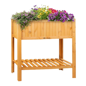
- Page 1 Altiplano Cubic Hochbeet Raised Bed Maceta elevada Platebande surélevée Vaso rialzato 10033605...
- Page 3 Sehr geehrter Kunde, wir gratulieren Ihnen zum Erwerb Ihres Gerätes. Lesen Sie die folgenden Hinweise sorgfältig durch und befolgen Sie diese, um möglichen Schäden vorzubeugen. Für Schäden, die durch Missachtung der Hinweise und unsachgemäßen Gebrauch entstehen, übernehmen wir keine Haftung. Scannen Sie den folgenden QR-Code, um Zugriff auf die aktuellste Bedienungsanleitung und weitere Informationen rund um das Produkt zu erhalten.
- Page 4 LIEFERUMFANG Vorder- und Rückwand (2 Stück) Standbein (4 Stück ) Seitenwände (2 Stück) Leiste (1 piece) Schraube 3,5 x Schraube 3,5 x Nagel (16 Stück) 30 mm 25 mm (24 Stück) (2 Stück)
- Page 5 Boden (1 Stück) Ablage (1 Stück) Innenteil (1 Stück)
-
Page 6: Montage
MONTAGE Schritt 1: Montieren Sie die Vorder- und Rückwand (2) und die Seitenwände (3) am oberen Ende der 4 Standbeine (1) und schrauben Sie diese mit 16 Schrauben (3,5 mm x 30 mm) fest. Schrauben 3,5 x 30 mm (16 Stück) - Page 7 Schritt 2: Montieren Sie die Ablage (5) im unteren Bereich der vier Standbeine (1) und schrauben Sie diese mit 8 Schrauben (3,5 mm x 30 mm) fest. Schrauben 3,5 x 30 mm (8 Stück)
- Page 8 Schritt 3: Legen Sie nun den Boden (4) von oben in das Hochbeet hinein.
- Page 9 Schritt 4: Befestigen Sie den Boden (4) mit der Leiste (7) von unten mit 2 Schrauben (3,5 mm x 25 mm) am Hochbeet. Schrauben 3,5 x 25 mm (2 Stück)
- Page 10 Schritt 5: Befestigen Sie das Innenteil (6) mit 16 Nägeln im Hochbeet.
- Page 11 Ihr Hochbeet ist nun fertig montiert und einsatzbereit.
-
Page 12: Scope Of Delivery
SCOPE OF DELIVERY Front and rear wall (2 pieces) Support leg (4 pieces ) Side walls (2 pieces) Bar (1 piece) Screw (3.5 mm x Screw (3.5 mm x 25 Nail (16 pieces) 30 mm) (24 pieces) (2 pieces) - Page 13 Bottom (1 piece) Shelf (1 piece) Inner part (1 piece)
- Page 14 ASSEMBLY Step 1: Assemble the front and rear panels (2) and the side panels (3) to the upper end of the 4 support legs (1) and screw them tight with 16 screws (3.5 mm x 30 mm). Screws 3.5 x 30 mm (16 pieces)
- Page 15 Step 2: Mount the shelf (5) in the lower area of the four support legs (1) and screw it tight with 8 screws (3.5 mm x 30 mm). Screws 3.5 x 30 mm (8 pieces)
- Page 16 Step 3: Now place the bottom (4) from above into the raised bed.
- Page 17 Step 4: Fasten the bottom (4) with the bar (7) to the raised bed from below with 2 screws (3.5 mm x 25 mm). Screws 3.5 x 25 mm (2 pieces)
- Page 18 Step 5: Fasten the inner part (6) to the raised bed with 16 nails.
- Page 19 Your raised bed is now fully assembled and ready for use.
-
Page 20: Contenido Del Envío
CONTENIDO DEL ENVÍO Pared delantera y trasera (2 piezas) Patas (4 piezas ) Paredes laterales (2 piezas) Tira (1 pieza) Tornillo 3.5 x Tornillo 3,5 x 25 mm Clavo (16 piezas) 30 mm (2 piezas) (24 piezas) - Page 21 Suelo (1 pieza) Estante (1 pieza) Parte interior (1 pieza)
-
Page 22: Montaje
MONTAJE Paso 1: Monte los paneles frontal y trasero (2) y los paneles laterales (3) en la parte superior de las 4 patas (1) y atorníllelos con 16 tornillos (3,5 mm x 30 mm). Tornillos 3,5 x 30 mm (16 piezas) - Page 23 Paso 2: Monte el estante (5) en la parte inferior de las cuatro patas (1) y atorníllelo con 8 tornillos (3,5 mm x 30 mm). Tornillos 3,5 x 30 mm (8 piezas)
- Page 24 Paso 3: Ahora coloque el fondo (4) en la cama elevada desde arriba.
- Page 25 Paso 4: Fije el fondo (4) a la cama elevada desde abajo con el listón (7) utilizando 2 tornillos (3,5 mm x 25 mm). Tornillos 3,5 x 25 mm (2 piezas)
- Page 26 Paso 5: Su lecho elevado está ahora completamente montado y listo para su uso.
- Page 27 La cama elevada ya está montada y lista para usar.
-
Page 28: Contenu De L'emballage
CONTENU DE L'EMBALLAGE Panneaux avant et arrière (2 pièces) Pied (4 pièces) Panneaux latéraux (2 pièces) Bande (1 pièce) Vis 3,5 x 30 mm Vis 3,5 x 25 mm Clou (16 pièces) (24 pièces) (2 pièces) - Page 29 Fond (1 pièce) Étagère (1 pièce) Partie intérieure (1 pièce)
- Page 30 MONTAGE Étape 1 : Assemblez les panneaux avant et arrière (2) et les panneaux latéraux (3) à l'extrémité supérieure des 4 pieds (1) et vissez-les avec 16 vis (3,5 mm x 30 mm). Vis 3,5 x 30 mm (16 pièces)
- Page 31 Étape 2 : Montez l'étagère (5) dans la partie inférieure des quatre pieds (1) et vissez-la avec 8 vis (3,5 mm x 30 mm). Vis 3,5 x 30 mm (8 pièces)
- Page 32 Étape 3 : Placez maintenant le fond (4) par le haut dans le potager surélevé.
- Page 33 Étape 4 : Fixez le fond (4) avec la bande (7) au potager surélevé par le bas avec 2 vis (3,5 mm x 25 mm). Vis 3,5 x 25 mm (2 pièces)
- Page 34 Étape 5 : Fixez la partie intérieure (6) au potager surélevé avec 16 clous.
- Page 35 Votre potager surélevé est maintenant entièrement assemblé et prêt à l'emploi.
-
Page 36: Volume Di Consegna
IT IT VOLUME DI CONSEGNA Pareti anteriore e posteriore (2 pezzi) Piedi d'appoggio (4 pezzi ) Pareti laterali (2 pezzi) Asta (1 pezzo) Viti 3,5 x 30 mm Viti 3,5 x 25 mm Chiodi (16 pezzi) (24 pezzi) (2 pezzi) - Page 37 Pannello di fondo (1 pezzo) Appoggio (1 pezzo) Componente interno (1 pezzo)
- Page 38 MONTAGGIO 1° passaggio: Montare le pareti anteriore, posteriore (2) e laterali (3) all'estremità superiore dei 4 piedi d'appoggio (1) e avvitarle saldamente con 16 viti (3,5 mm x 30 mm). Viti 3,5 x 30 mm (16 pezzi)
- Page 39 IT IT 2° passaggio: Montare l'appoggio (5) sulla parte inferiore dei quattro piedi d'appoggio (1) e avvitarlo saldamente con 8 viti (3,5 mm x 30 mm). Viti 3,5 x 30 mm (8 pezzi)
- Page 40 3° passaggio: Inserire dall'alto il pannello di fondo (4) nell'aiuola rialzata.
- Page 41 4° passaggio: Fissare dal basso il pannello di fondo (4) all'aiuola rialzata con l'asta, utilizzando 2 viti (3,5 mm x 25 mm). Viti 3,5 x 25 mm (2 pezzi)
- Page 42 5° passaggio: Fissare il componente interno (6) all'aiuola rialzata con 16 chiodi.
- Page 43 L'aiuola rialzata è completamente montata e pronta all'uso.
- Page 44 HERSTELLER Manufacturer | Fabricante | Fabricant | Produttore Chal-Tec GmbH, Wallstraße 16, 10179 Berlin, Deutschland (Germany). IMPORTEUR FÜR GROSSBRITANNIEN Importer for Great Britain | Importador para Gran Bretaña | Importateur pour la Grande Bretagne | Importatore per la Gran Bretagna Berlin Brands Group UK Limited PO Box 42 272 Kensington High Street...
Need help?
Do you have a question about the Altiplano Cubic and is the answer not in the manual?
Questions and answers