Advertisement
Quick Links
English Instruction for N10 Multifunctional Tester
Model: N10
Dear user:
In order to let you know all the functions of this product faster, get a better user experience, and
avoid misoperation, please read this manual carefully before use and keep it for future reference.
Advertisement

Subscribe to Our Youtube Channel
Summary of Contents for Makerfire N10
- Page 1 English Instruction for N10 Multifunctional Tester Model: N10 Dear user: In order to let you know all the functions of this product faster, get a better user experience, and avoid misoperation, please read this manual carefully before use and keep it for future reference.
-
Page 2: Product Parameters
Product Parameters Model: N10 Product weight: 20.5g (net weight) Input voltage: 3.8V-30V Voltage measurement resolution: 0.01V Input current: 0-3.000A Current measurement resolution: 0.001A Capacity measurement range: 0-99999Ah Voltage measurement accuracy: ±1% Current measurement accuracy: ±1% Energy measurement range: 0-99999Wh Load impedance measurement range: 1.5 Time measurement range: 0-99 hos 59 mics 59 seds Ω-9999.9Ω... -
Page 3: Function Interface
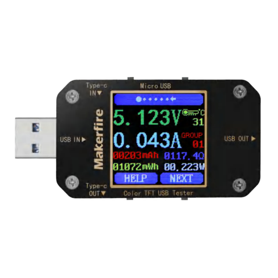
Function Interface Type-c interface (support PD fast charging) Micro USB interface Multi-function buttons Multi-function buttons Type-c interface (support PD fast charging) USB female interface USB male interface 1.44-inch color LCD display... - Page 4 Instructions Main interface 1 (main measurement interface) 1. Voltage measurement value 2. Current measurement value 3. Historical cumulative capacity value 4. Historical cumulative energy value 5. Temperature display 6. Data group number 7. Load Equivalent Impedance 8. Power measurement Short press the "Help" button, the interface will display as above: Long press the "Next"...
- Page 5 Main interface 2 (quick charging identification interface) 1. D+: DP, data positive signal 2. D-: DM, data negative signal 3. Mode display: QC2.0, QC3.0 mode Short press the "Next" button to switch to the main 3 (data recording interface) Main interface 3 (data recording interface) 1.
- Page 6 Main interface 4 (line resistance measurement interface) 1. The voltage and current value when the tester is directly connected to the power supply (recommended to connect to a fixed voltage and current; only support the power input from the USB-A male terminal, and the output terminal is USB-A female) 2.
- Page 7 powered on next time. Short press the "Next" button to switch to the main interface 5 (voltage curve interface) Main interface 5 (voltage curve interface) This interface is the waveform diagram of the measured voltage, which automatically changes the range within the measurement range of 3.8-30.0V, and displays the voltage fluctuation in real time.
- Page 8 Main interface 7 (setting interface) 1. Delay off screen time 2. Screen brightness 3. Temperature unit switching Long press the "Next" button to select the delay screen off time, brightness level, and temperature unit switching in turn. Long press the "Next" button to enter the screen off time setting, select the corresponding number and display it in reverse, and short press to cyclically modify the value, , the values are changed in a sequence of 10 values from 0 to 9, where 0 is always on.
- Page 9 Warm tips This product supports forward and reverse input and output detection, current flow direction indication, and alarm reminder functions. Temperature alarm: exceeds 45℃, the temperature display will flash; voltage alarm: less than 3.8V or greater than 30V, the voltage display will flash; current alarm: greater than 3A , the current display will flash.
Need help?
Do you have a question about the N10 and is the answer not in the manual?
Questions and answers