
Related Manuals for Scantech XC Series

Summary of Contents for Scantech XC Series
- Page 1 series expansions with special functions Operate Manual Xinje Electronic Co., Ltd.
-
Page 3: Table Of Contents
Catalog 1. MODULES INFORMATION ........................1 2. PID FUNCTION ............................. 4 3. ANALOG INPUT MODULE XC-E8AD ...................... 5 4. ANALOG INPUT/OUTPUT MODULE XC-E4AD2DA ................13 5. ANALOG OUTPUT MODULE XC-E4DA ....................21 6. PT100 TEMPERATURE PID CONTROL MODULE XC-E6PT-P ............25 7. -
Page 5: Modules Information
1. Modules information 1. Basic Characteristics XC series PLCs not only have strong functions of logic operation, data operation, high speed processing etc. but also functions of A/D, D/A conversion, PID adjustment. With the expansions of analog input module, analog output module, temperature control module etc, XC series PLCs are widely used in the control system of temperature, flow, liquid level, pressure. - Page 7 4. General Specification Operating Environment No corrosive gas ℃ ℃ Ambient Temperature 0 ~60 Store Temperature -20~70℃ Ambient Humidity 5~95% Store Humidity 5~95% Can be fixed with M3 screw or directly installed on orbit of Installation DIN46277 (width: 35mm) Size 63mm×102mm×73.3mm 5.
-
Page 8: Pid Function
2. PID Function 1. Brief introduction of PID function Among XC series PLC special modules, digital input module (A/D module) and temperature control module both have PID control function which is widely used. There are only four parameters (Kp, Ki, Kd and Diff) should be set. -
Page 9: Analog Input Module Xc-E8Ad
3. Analog input module XC-E8AD 1. Specification 14 bits high precision analog input 8 channels analog input: The first four channels are current input (0~20mA, 4~20 mA); The left 4 channels are voltage input (0~5V, 0~10V) As special function module of XC, up to 7 models can be connected. - Page 10 2. Input address XC series analog module doesn’t occupy I/O unit, the converted data is directly transferred to PLC register. Each channel address: I/O address list Register address of expansion module 1: PID Parameters: Kp, PID output PID start/stop Ki, Kd, control range...
- Page 11 ID305 ID313 Y305 QD305 ID306 ID314 Y306 QD306 ID307 ID315 Y307 QD307 Register address of expansion module 4: PID parameters: Kp, PID output PID start/stop Ki, Kd, control range Channel AD signal Preset value value control bit Diff, dead range “Death”...
- Page 12 ID605 ID613 Y605 QD605 ID606 ID614 Y606 QD606 ID607 ID615 Y607 QD607 Register address of expansion module 7: PID parameters: Kp, PID output PID start/stop Ki, Kd, control range Channel AD signal Preset value value control bit Diff, dead range “Death”...
- Page 13 The following, we take module 1 as example to describe the setting format: Register FD8250: Channel 1 Channel 0 Bit7 Bit6 Bit5 Bit4 Bit3 Bit2 Bit1 Bit0 00: 1/2 filter 00: 1/2 filter 01: not filter 0:0~20mA 01: not filter 0:0~20mA 10: 1/3 filter 1:4~20mA...
- Page 14 Layout diagram: 5. Analog/digital convert chart The relationship between input analog and converted digital quantity is showed in the following chart: Current mode of Channel 0~Channel 3: 0~20mA analog input 4~20mA analog input...
- Page 15 Voltage mode of Channel 4 ~ Channel 7: 0~5V analog input 0~10V analog input 6. Programming E.g. 1) Real time read unit 1 XC-E8AD 8 channels’ data M8000 ID100 Write channel 0’s data into data register D0 ID101 Write channel 1’s data into data register D1 ID102 Write channel 2’s data into data register D2 ID103...
- Page 16 E.g.2) Application of PID control in AD modules The following, we take XC-E8AD channel 0 as an example: M8000 ID100 Write channel 0’s data into data register D10 D4000 QD100 Channel 0’s preset value is in register D4000 QD108 Set parameter Kp to 30 Set parameter Ki to 10 QD109 Set parameter Kd to 300...
-
Page 17: Analog Input/Output Module Xc-E4Ad2Da
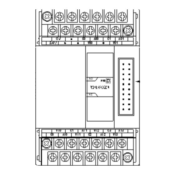
4. Analog input/output module XC-E4AD2DA 1. Specification 4 channels 14 bits analog input and 2 channels 12 bits analog output 4 channels selectable voltage 0~5V, 0~10V, current 0~20mA, 4~20mA input and 2 channels selectable voltage 0~5V, 0~10V, current 0~20mA, 4~20mA output. - Page 18 2.The assignment of I/O address XC series analog modules do not occupy I/O units, the converted data is directly transferred into PLC register, analog output is also directly offered by PLC register. Register’s address of expansion 1: PID parameter: Kp,...
- Page 19 Register’s address of expansion 4: PID parameter: Kp, PID output PID start/stop Channel AD signal The set value Ki, Kd, control range value control bit Diff, dead area Death ID400 ID404 Y400 QD402 Kp: QD406 Ki: QD407 ID401 ID405 Y401 QD403 Kd: QD408 ID402...
- Page 20 Register’s address of expansion 7: PID parameter: Kp, PID output PID start/stop Channel AD signal The set value Ki, Kd, control range value control bit Diff, dead area Death ID700 ID704 Y700 QD702 Kp: QD706 Ki: QD707 ID701 ID705 Y701 QD703 Kd: QD708 ID702...
- Page 21 The following, we take module 1 as an example to show how to set: Register FD8250: Channel 1 Channel 0 Bit7 Bit6 Bit5 Bit4 Bit3 Bit2 Bit1 Bit0 00: 1/2 filter 0:0~10V 00: 1/2 filter 0:0~10V 0: voltage 0: voltage 1:0~5V 1:0~5V 01: not filter...
- Page 22 5. Analog digital conversion chart The relationship between input analog and converted digital value is showed in the following chart: 0~5V analog input 0~10V analog input 0~20mA analog input 4~20mA analog input...
- Page 23 The relationship between output digital value and its corresponding analog data is showed in the following chart: 0~5V analog output 0~10V analog output 0~20mA analog output 4~20mA analog output When input data exceeds K4095, analog output will keep the max value of 5V, 10V or 20mA. 6.
- Page 24 E.g.2) Applied method of PID (take expansion 1’s channel 0 as example) M8000 Write channel 0 data into data register D10 ID100 Channel 0 preset value is register D4000 D4000 QD100 Set parameter Kp to 30 QD106 Set parameter Ki to 10 QD107 Set parameter Kd to 300 K300...
-
Page 25: Analog Output Module Xc-E4Da
5. Analog output module XC-E4DA 1. Specification 12 bits high precision analog output 4 channels selectable voltage 0~5V, 0~10V, current 0~20mA, 4~20mA output As special function module of XC, 7 modules could be connected Items Voltage output Current output Analog output bound DC0~5V, 0~10V... - Page 26 2. Assignment of Output address XC series analog module does not occupy I/O units, the converted data is directly transferred into PLC register. The output channels corresponding PLC register address is: Output address list Channel No.1 unit No.2 unit No.3 unit No.4 unit...
- Page 27 4. Exterior connection When make exterior connection, please see the following items: When connect external +24V power, please use the 24V power on PLC main unit to avoid interference. To avoid interference, please use shield cable and single point ground with the shield layer. ...
- Page 28 0~20mA analog output 4~20mA analog output When the digital data exceed K4095, D/A analog output data will keep 5V, 10V or 20mA. 6. Programming Real-time write data into 4 channels M8000 QD100 Write data into data register D10 and send to channel 0 QD101 Write data into data register D11 and send to channel 1 QD102...
-
Page 29: Pt100 Temperature Pid Control Module Xc-E6Pt-P
6. Pt100 temperature PID control module XC-E6PT-P 1. Specification Platinum thermal resistance input, Pt100 6 channels input, 6 channels output 2 groups PID parameters (every 3 channels have one group of PID parameters) 1mA constant current output, will not be affected by the exterior environment ... - Page 30 2. Assignment of input address XC series analog modules don’t occupy I/O units; the converted data is directly transferred into PLC register, channel register address: Table of input definition address: Channel 1#module 2#module 3#module 4#module 5#module 6#module 7#module ID100 ID200...
- Page 31 Start signal (Y): When Y is 0, close PID control; when Y is 1, start PID control 3. Setting of input filter 1) Every input of expansion has filter options, set via special FLASH data register FD in PLC. See the following chart: channel address Take 1# module as an example:...
- Page 32 4. Exterior connection About the external wiring, please see the following items: When connect +24V power, please use 24V power on PLC main unit to avoid interference. To avoid interference, please use shield cable to ground. Input connection: COM0 COM1 COM2...
- Page 33 The output circuit is as the following: Take channel 0 and channel 1 as an example: 6. Programming Program with the first channel M8000 Set channel 0 preset temperature to 800 (80 degrees) K800 QD100 Set channel 0 parameter Kp to 30 QD106 Set channel 0 parameter Ki to 5 QD107...
-
Page 34: K Type Thermocouple Temperature Pid Control Module Xc-E6Tc-P
7. K type thermocouple temperature PID control module XC-E6TC-P 1. Specification K type thermocouple sensor signal input 6 channels input, 6 channels output 2 groups PID parameters (every 3 channels have group parameters) Built-in cold-terminal compensation circuit ... - Page 35 2. Assignment of input address XC series analog modules don’t occupy I/O units, the converted data is directly transferred into PLC register, and channels corresponding register address are: Input address list Channel Expansion Expansion Expansion Expansion Expansion Expansion Expansion ID100...
- Page 36 Last 3 QD111 QD211 QD311 QD411 QD511 QD611 QD711 channels parameter I Last 3 QD112 QD212 QD312 QD412 QD512 QD612 QD712 channels parameter D QD113 QD213 QD313 QD413 QD513 QD613 QD713 Last 3 channels temperature control range ﹡Note: For new XC-6TC-P produced after August, 2008, please use new manual XC-6TCA-P Manual.
- Page 37 Channel 1 Channel 0 Bit7 Bit6 Bit5 Bit4 Bit3 Bit2 Bit1 Bit0 00: 1/4 filter 00: 1/4 filter 01: no filter 01: no filter 10: 1/2 filter 10: 1/2 filter 11: 1/3 filter 11: 1/3 filter Channel 3 Channel 2 Bit15 Bit14 Bit13...
- Page 38 COM0 COM1 COM2 0 1 2 3 TC0+ TC1+ TC2+ TC3+ TC4+ TC5+ TC0- TC1- TC2- TC3- TC4- TC5- Output terminal For transistor output terminals, please use DC5V~30V power supply. Circuit insulation PLC internal circuit and output transistor is optical insulation with optical coupling device. Each public module is separate.
- Page 39 6. Program Program with the first channel M8000 K800 QD100 Set channel 0 value to 800 (80 degrees) QD106 Set channel 0 parameter Kp to 30 QD107 Set channel 0 parameter Ki to 5 Set channel 0 parameter Kd to 500 K500 QD108 Set channel 0 parameter Diff to 150...
-
Page 40: Xc-E3Ad4Pt2Da
8. XC-E3AD4PT2DA 1. Specifications 3 channels 14 bits current input, 4 channels PT100 temperature input and 2 channels 10 bits voltage output 3 channels current 0~20mA, 4~20mA input (selectable) and 2 channels voltage 0~5V, 0~10V output (selectable), set via the software ... - Page 41 [Extend Port]: Connect to other expansions 2. I/O address XC series analog modules do not occupy I/O units, the converted value is sent to PLC register directly. Analog output is also offered by PLC register. The first expansion registers address:...
- Page 42 The third expansion registers address: PID Output PID start/stop PID parameter: Kp, Channel AD Signal Preset Value Value Ki, Kd, Diff, Death ID300 ID307 Y300 QD302 ID301 ID308 Y301 QD303 ID302 ID309 Y302 QD304 Kp------- QD309 PID Output PID start/stop Ki------- QD310 Channel...
- Page 43 The fifth expansion registers address: PID Output PID start/stop PID parameter: Kp, Channel AD Signal Preset Value Value Ki, Kd, Diff, Death ID500 ID507 Y500 QD502 ID501 ID508 Y501 QD503 ID502 ID509 Y502 QD504 Kp------- QD509 PID Output PID start/stop Ki------- QD510 Channel...
- Page 44 PID Output PID start/stop Diff------ QD712 Channel PT Signal Preset Value Value Death---- QD713 ID703 ID710 Y703 QD705 ID704 ID711 Y704 QD706 ID705 ID712 Y705 QD707 ID706 ID713 Y706 QD708 Channel DA Signal QD700 QD701 Description: Start signal (Y): when Y is 0, close PID control, when Y is 1, start PID control 3.
- Page 45 Register FD8250: Input CH 1 (AD) Input CH 0 (AD) Bit7 Bit6 Bit5 Bit4 Bit3 Bit2 Bit1 Bit0 00: 1/2 filter 00: 1/2 filter 01: no filter 0:0~20mA 01: no filter 0:0~20mA 10: 1/3 filter 1:4~20mA 10: 1/3 filter 1:4~20mA 11: 1/4 filter 11: 1/4 filter Input CH 3 (PT)
- Page 46 The 0~20mA or 4~20mA output of the module need connect to external 24V power supply. The module adjusts the circuit current according to the QD value. The module doesn’t produce current itself. 5. Analog/Digital conversion Diagram The relationship between the analog input and the converted digital value is shown as below: 0~20mA analog input 4~20mA analog input...
- Page 47 The relationship between the digital input and corresponding analog output is shown as below: 0~5V analog output 0~10V analog output When the output value is larger than K1023, D/A converted analog value will remain 5V or 10V. The output value of PT100 is shown as below: PT100 Input 6.
- Page 48 M8000 Write AD value of CH0 to data register D0 ID100 ID101 Write AD value of CH1 to data register D1 ID102 Write AD value of CH2 to data register D2 ID103 Write temperature value of CH3 to data register D3 ID104 Write temperature value of CH4 to data register D4 ID105...
- Page 49 M8000 ID100 Write AD value from CH0 to data register D10 D4000 QD102 Write the AD value from CH0 to register D4000 QD109 Set parameter Kp to 30 Set parameter Ki to 10 QD110 Set parameter Kd to 300 K300 QD111 Set parameter Diff to 100 K100...
-
Page 50: Analog Input Module Xc-E4Ad
[Expansion Port]: Connect to other expansion modules 2. Assignment of I/O address XC series expansions do not occupy I/O units; the converted value is transferred to PLC register directly. Analog input is also offered by PLC register. Register address of expansion 1:... - Page 51 PID Parameters: Kp, PID Output PID Start/Stop Control Channel AD Signal Preset Value Value Control Bit Range Diff, Dead Range “Death” ID100 ID104 Y100 QD102 Kp------- QD106 Ki------- QD107 ID101 ID105 Y101 QD103 Kd------- QD108 ID102 ID106 Y102 QD104 Diff------ QD109 Death---- QD110...
- Page 52 Register address of expansion 5: PID Parameters: Kp, PID Output PID Start/Stop Control Channel AD Signal Preset Value Value Control Bit Range Diff, Dead Range “Death” ID500 ID504 Y500 QD502 Kp------- QD506 Ki------- QD507 ID501 ID505 Y501 QD503 Kd------- QD508 ID502 ID506 Y502...
- Page 53 Channel’s address Module 0CH~3CH Take 1# expansion as example: 1# expansion FD8250 FD8250 H O O O O 2# expansion FD8258 3# expansion FD8266 4# expansion FD8274 5# expansion FD8282 6# expansion FD8290 7# expansion FD8298 Note:As shown in the preceding table, every register set 4 channels mode, each register has 16 bits, from low to high, every 4 bits set 1 channel mode.
- Page 54 5. Analog digital conversion diagram The relationship between input analog and converted digital is shown in the following chart: 0~5V analog input 0~10V analog input 0~20mA analog input 4~20mA analog input...
- Page 55 6. Programming E.g.1 Real-time read the 4 channels data, write 2 channels data (take expansion 1 as an example) M8000 ID100 Read channel 0 data to register D0 ID101 Read channel 1 data to register D1 Read channel 2 data to register D2 ID102 输入第...
- Page 56 M8000 Read channel 0 data to register D10 ID100 Set channel 0 output value D4000 QD100 Set parameter Kp to 30 QD106 Set parameter Ki to 10 QD107 Set parameter Kd to 300 K300 QD118 K100 QD119 Set adjustment range Diff to 100 Set control dead area to 200 K200 QD110...
-
Page 57: Xc-E2Da
[Extend port]: connect to other expansions. 2. The assignment of I/O address XC series analog modules don’t occupy I/O units, the converted value is sent to PLC register directly. Analog output is also offered by PLC register. Register address of expansion 1~7:... - Page 58 Channel 1 unit 2 unit 3 unit 4 unit 5 unit 6 unit 7 unit QD100 QD200 QD300 QD400 QD500 QD600 QD700 QD101 QD201 QD301 QD401 QD501 QD601 QD701 3. Working mode setting 1) Expansion I/O has voltage 0 ~ 5V, 0 ~ 10V, current 0 ~ 20mA, 4 ~ 20mA for selection, set the modes through the PLC internal special FLASH registers FD.
- Page 59 4. Analog/Digital conversion diagram The relationship between the input analog value and the converted digital value is shown as below: When the output value is larger than K4095, D/A converted analog value will remain 5V, 10V or 20mA.
- Page 60 6. Program eg.1) Real-time write data to 2 channels Set channel 0 output value Set channel 1 output value...
- Page 61 信捷科技电子有限公司 Xinje Electronic Co., Ltd. 江苏省无锡市蠡园开发区 4th Floor Building 7,Orignality Industry park, 创意产业园 7 号楼四楼 Liyuan Development Zone, Wuxi City, 邮编: 214072 Jiangsu Province 214072 电话: (0510)85134136 Tel: (510)85134136 www.xinje.com/0 传真: (0510)85111290 Fax: (510)85111290...
Need help?
Do you have a question about the XC Series and is the answer not in the manual?
Questions and answers