
Related Manuals for Kramer 8105


Summary of Contents for Kramer 8105
- Page 1 Operator’s Manual Wheel loader 8105 8115 / 8115L Machine model 352-03S / 352-04S / 352-04L From serial no. 352 03 0001 / 352 04 0001 Version Doc. Number 1000328043 Language [en]...
- Page 2 Violations of legal regulations, in particular of the copyright protection, shall be subject to civil and criminal prosecution. KRAMER-WERKE GmbH keep abreast of the latest technical developments and constantly improve their products. For this reason, we may from time to time need to make changes to figures and descriptions in this documentation that do not reflect products that have already been delivered and that will not be implemented on these machines.
-
Page 3: Table Of Contents
Table of contents Table of contents Table of contents EC Declaration of Conformity ........................EG-1 1 Preface 1.1 Operator’s Manual ..........................1-1 1.2 Warranty and liability ..........................1-4 2 Safety 2.1 Safety symbols and signal words ......................2-1 2.2 Conduct and safety instructions ......................2-2 2.3 Qualification of operating and maintenance personnel................. - Page 4 Table of contents 7 Maintenance 7.1 Information on maintenance ......................... 7-1 7.2 Maintenance overview .......................... 7-3 7.3 Fluids and lubricants........................... 7-12 7.4 Maintenance accesses ........................7-17 7.5 Cleaning and maintenance ......................... 7-18 7.6 Lubrication work..........................7-24 7.7 Fuel system ............................7-27 7.8 Engine lubrication system........................
- Page 5 EC Declaration of Conformity EC Declaration of Conformity EC Declaration of Conformity Original declaration of conformity Manufacturer Kramer-Werke GmbH, Wacker-Neuson-Str. 1, D-88630 Pfullendorf Product Vehicle designation Wheel loader 352 model Ausführung 352-03S 352-04S (352-04L) Trade name 8105 8115 (8115L) Serial number...
-
Page 6: Ec Declaration Of Conformity
EC Declaration of Conformity EG-2 BA 35203_04 * 3.0 * 35203_04_EG_Konformitaet.fm... -
Page 7: Preface
Operator’s Manual and in particular the safety instructions. The buyer/operating company is responsible for the operators’ training in safe working on and with the machine. Kramer-Werke GmbH recommends repeating training at regular intervals. The buyer/operating company is responsible for ensuring that any additional safety regulations applicable in the country of use of the machine are followed. - Page 8 1 Preface Important information on this Operator’s Manual • The operator's manual and any amendments form part of the machine and must always be available at the place of use of the machine. • Store this Operator’s Manual in the storage compartment or net provided for this in the cabin.
- Page 9 Preface 1 Abbreviations Abbreviation Explanation Abbreviation Explanation ROPS Roll Over Protective Structure (opt) Option Ripper tooth Fig. Figure Society of Automotive Engineers, General National Type Approval (Germany) viscosity class for motor oil certification StVZO Automatic Transmission Fluid (German (lubricant) German Traffic Regulation traffic Order no.
-
Page 10: Warranty And Liability
1 Preface Warranty and liability Warranty claims can be made only if the conditions of warranty have been observed. They are included in the General Conditions of Sales and Delivery for new machines and spare parts sold by the dealers. Furthermore, the instructions in this Operator’s Manual must be observed. -
Page 11: Safety
Safety Safety 2 Safety Safety symbols and signal words Explanation The following symbol identifies safety instructions. It is used for warning against potential personal risk or danger. DANGER DANGER identifies a situation causing death or serious injury if it is not avoided. -
Page 12: Conduct And Safety Instructions
2 Safety Conduct and safety instructions Prerequisites for operation • The machine has been designed and built in accordance with state-of-the-art standards and the recognized safety regulations. Nevertheless, its use can cause danger to the operator or other persons, or damage to the machine. •... -
Page 13: Qualification Of Operating And Maintenance Personnel
Safety 2 Qualification of operating and maintenance personnel Owner’s duties • Only allow specifically authorized, trained and experienced persons to operate, drive and perform maintenance on the machine. • Do not allow persons to be trained or instructed by anyone other than an authorized and experienced person. -
Page 14: Operation
2 Safety Operation Preparatory measures • Operation is only allowed with correctly installed and intact protective structures. • Keep the machine clean. This reduces injury, accident and fire hazards. • Safely store objects you carry with you in the places provided for this (for example in the storage compartment, drinks holder). - Page 15 Safety 2 Job site • The operator is responsible for other persons. • Before starting work, familiarize yourself with the job site. This applies to, for example: - Obstacles in the job site and machine travel area - Any barriers separating the job site from public roads - Soil weight-bearing capacity - Existing overhead and underground lines - Special operating conditions (for example dust, steam, smoke, asbestos)
- Page 16 2 Safety Carrying passengers • Carrying passengers with the machine is PROHIBITED. • Carrying passengers on/in attachments/tools is PROHIBITED. • Carrying passengers on/in trailers is PROHIBITED. Mechanical integrity • The operator and owner are obligated to operate the machine only in a safe and working condition.
- Page 17 Safety 2 Machine travel on public roads/sites • The specific national driving license is required. • Observe the national regulations (for example the road traffic regulations) during machine travel on public roads/sites. • Ensure that the machine is in compliance with the national regulations. •...
-
Page 18: Lifting Gear Applications
2 Safety Lifting gear applications Requirements • Have loads fastened and the operator guided by a qualified person having specific knowledge of lifting gear applications and the usual hand signals. • The person giving instructions to the operator must stay in visual contact with the operator when fastening, guiding or removing the load (maintain visual contact). - Page 19 Safety 2 Lifting gear applications • The machine must be certified for lifting gear applications. • Observe the national regulations for lifting gear applications. • Lifting gear applications are procedures involving raising, transporting and lowering loads with the help of lifting and fastening gear. •...
-
Page 20: Trailer Operation
2 Safety Trailer operation Trailer operation • The machine must be certified for trailer operation. • Observe the national regulations for trailer operation. • The specific national driving license is required. • Carrying passengers on/in trailers is PROHIBITED. • Observe the maximum permissible vertical and trailer load. •... -
Page 21: Attachment Operation
Safety 2 Attachment operation Attachments • Use only attachments that are certified for the vehicle or its protective device (for example a shatter protection). • All other attachments require the machine manufacturer’s release. • The danger zone and the work zone depend on the attachment used – see the Operator’s Manual of the attachment. -
Page 22: Towing, Loading And Transporting
2 Safety Towing, loading and transporting Towing • Seal off the danger zone. • Ensure that no one is near the towing bar or cable. The safety distance is equal to 1.5 times the length of the towing equipment. • Observe the mandatory transport position, permissible speed and itinerary. - Page 23 Safety 2 Crane-lifting • Seal off the danger zone. • The crane and the lifting gear must have suitable dimensions. • Observe the machine’s overall weight – see “Technical data”. • Wear protective clothing and equipment when fastening, guiding and removing the machine (for example a hard hat, safety glasses, safety boots).
- Page 24 2 Safety Transportation • For the safe transportation of the machine: - The transport vehicle must have a sufficient load capacity and platform – see “Technical data” - The maximum weight rating of the transport vehicle must not be exceeded. •...
-
Page 25: Maintenance
Safety 2 Maintenance Maintenance • Observe the intervals prescribed by law and those specified in this Operator’s Manual for routine checks/inspections and maintenance. • For inspection and maintenance, ensure that all tools and service center equipment are adapted to the performance of the task described in this Operator’s Manual. - Page 26 2 Safety Preparatory measures • Attach a warning label to the control elements (for example “Machine being serviced, do not start”). • Before performing assembly work on the machine, support the areas to be serviced and use suitable lifting and supporting equipment for the replacement of parts over 9 kg (20 lbs.).
- Page 27 Safety 2 Modifications and spare parts • Do not modify the machine and the work equipment/attachment (for example, the safety devices, lighting, tires, straightening and welding work). • Modifications must be approved by the manufacturer and performed by an authorized service center. •...
-
Page 28: Measures For Avoiding Risks
2 Safety 2.10 Measures for avoiding risks Tyres • Have repair work on the tires only performed by trained technical personnel. • Check the tires for correct pressure and visible damage (for example cracks, cuts). • Check the wheel nuts for tightness. •... - Page 29 Safety 2 Battery • Batteries contain caustic substances (for example sulfuric acid). When handling the battery observe the specific safety instructions and regulations relevant to accident prevention. • A volatile oxyhydrogen mixture forms in batteries during normal operation and especially during charging. Always wear gloves and eye protection when working with batteries.
- Page 30 2 Safety Handling oil, grease and other substances • When handling oil, grease and other chemical substances (for example the battery acid, coolant), observe the safety data sheets. • Wear appropriate protective equipment (for example protective gloves, safety glasses). • Be careful when handling hot consumables –...
- Page 31 Safety 2 Working near electric supply lines • Before performing any work, the operator must check whether there are any electric supply lines in the job site. • If there are electric supply lines, only a machine with cabin may be used (Faraday cage).
- Page 32 2 Safety Behavior during thunderstorm • Stop machine operation if a thunderstorm is gathering, stop the machine, secure and leave it, and avoid being near it. Noise • Observe the noise regulations (for example during applications in enclosed premises). • Bear in mind external sources of noise (compressed-air hammer, concrete saw).
-
Page 33: Introduction
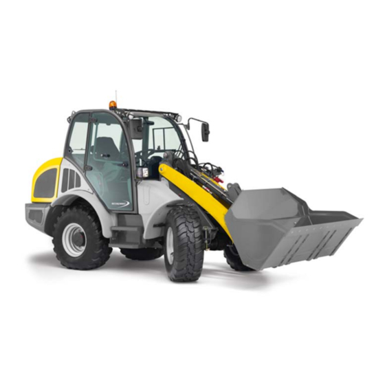
Introduction Introduction 3 Introduction Machine overview Fig. 1 Designation Designation Bracket for warning stripe (option) 20 Towing gear Headlights (left/right) with turn indicators 21 Protective FOPS screen (option) Door arrester 22 4 x eye hooks for removing the cabin Handle for access (left/right) 23 Rotating beacon (option) Front left/right working lights (option) 24 Rear hooks for loading/tying down the... - Page 34 Letters S or L in the model designation identify the loader unit version: • S = standard loader unit • L = higher loader unit Model designation Trade name 352-03S 8105 352-04S 8115 352-04L 8115L BA 35203_04 * 3.0 * 35203_04_03_Einleitung.fm...
-
Page 35: Brief Description Of Machine
Introduction 3 Brief description of machine Main components of machine • Sturdy steel sheet frame; Engine stored on suspension elements. • ROPS/FOPS tested cabin (roll-over/falling object protection); Category I (standard), category II (optional) – see chapter 4 “Cabin/control stand” on page 4-1. - Page 36 3 Introduction Hydrostatic drive The diesel engine permanently drives a gear pump (variable displacement pump), whose oil flow is sent to a hydraulic motor on the transfer gearbox (standard - 20 km/h/12.43 mph) or to a high-speed gearbox (option – 30 and 40 km/h/18.64 and 24.85 mph).
-
Page 37: Information And Regulations On Use
Introduction 3 Information and regulations on use General information on the machine This machine is a versatile and powerful helper on construction sites, in agriculture and for recycling applications. The wide range of attachments accounts for the numerous applications of the machine: as a snowplow, a construction machine, a forklift truck for applications with palletized goods, or as a tractor for transport applications in agriculture (agriculture and forestry certification). - Page 38 3 Introduction Designated use The machine can be used as a self-propelled work machine or tractor if registered accordingly (LoF agricultural or forestry registration). EC test number, see page – see “Type label” on page 3-24. The available and authorized attachments will decide in the first place how the machine is used.
- Page 39 Introduction 3 Improper use Not using the machine according to its designated use means that it is used for an application that is not specified by the manufacturer. Therefore, this is misuse in the terms of the Machine Guideline. Alone the user, and not the manufacturer, shall be liable for damage resulting from this.
- Page 40 3 Introduction Driving license Wheel loaders may be driven on public roads only if the operator has a driving licence as defined by national traffic regulations. In Germany, § 5 StVZO (German traffic regulations) requires the following driving licenses for machine operation: •...
- Page 41 Introduction 3 Machine inspections In Germany, legislation, supplemented by the technical rules for operational safety (TRBS) 1201, requires all machine operators to have all machines and equipment inspected regularly (BGV A1/BetrSichV §10). Inspections must be performed as required, but at least once a year, by an expert and must be documented in written form.
- Page 42 3 Introduction On-board equipment In Germany, §53 StVZO (German road traffic regulations) requires the following equipment to be supplied by the operating company and to be fitted on the machine: • 1 warning triangle with design certification • 1 warning light with design certification •...
- Page 43 • Different quickhitches are available for the machine. Refer to the following tables for the corresponding attachments and the specific requirements: Attachments for Kramer quickhitch on page 3-12, Attachments for SKID STEER quickhitch on page 3-19, Attachments for EURO quickhitch on page...
- Page 44 3 Introduction Attachments for Kramer quickhitch NOTICE Damage to the machine due to the use of uncertified attachments! ► Use only attachments that are certified for the existing quickhitch and that are fitted with a load diagram certified for the specific attachment.
- Page 45 Introduction 3 KRAMER attachments model 352-03 (overview) Dimension Machine Part no. Capacity Attachment model (model ) (ft3) mm (in) Approved attachments for machine travel on public roads (Federal Republic of Germany) Loosening, picking up, 2050 (80.70) transporting and loading Standard bucket...
- Page 46 3 Introduction Dimension Machine Part no. Capacity Attachment model (model ) (ft3) mm (in) Non-approved attachments for machine travel on public roads (Federal Republic of Germany) Standard bucket, however with benefits 1844 (72.59) 0,6 / 0,75 2, 9 Side swing bucket 352-03 S 1000176121 for filling and backfilling without RZ...
- Page 47 Introduction 3 Dimension Machine Part no. Capacity Attachment model (model ) (ft3) mm (in) Non-approved attachments for machine travel on public roads (Federal Republic of Germany) 3-point adapter 1000251812 Installing special CAT II 352-03 S – – with drive 1000251813 attachments (for example a mower) Quickhitch triangle...
- Page 48 3 Introduction KRAMER attachments model 352-04 (overview) Dimension Machine Part no. Capacity Attachment model (model ) (ft3) mm (in) Approved attachments for machine travel on public roads (Federal Republic of Germany) Loosening, picking up, 2150 (84.64) 1000154387 transporting and loading...
- Page 49 Introduction 3 Dimension Machine Part no. Capacity Attachment model (model ) (ft3) mm (in) Non-approved attachments for machine travel on public roads (Federal Republic of Germany) Standard bucket, however with benefits 352-04 S 2044 (80.48) for filling and backfilling 4, 10 Side swing bucket 1000176655 –...
- Page 50 3 Introduction Dimension Machine Part no. Capacity Attachment model (model ) (ft3) mm (in) Non-approved attachments for machine travel on public roads (Federal Republic of Germany) 352-04 S Sidewalk and street 4, 11 Rotary broom 1000291632 – – 352-04 L cleaning 1000336399 4, 13, 14...
- Page 51 Introduction 3 Attachments for SKID STEER quickhitch The machine manufacturer has not released any attachments for this quickhitch! NOTICE Damage to machine due to attachments that have not been released. ► If attachments that are not released are used, conformity (stability test) in accordance with the EC machine guideline or the EN 474-3 standard must be checked and documented by an authorized service centre.
- Page 52 3 Introduction Attachments for EURO quickhitch The machine manufacturer has not released any attachments for this quickhitch! NOTICE Damage to machine due to attachments that have not been released. ► If attachments that are not released are used, conformity (stability test) in accordance with the EC machine guideline or the EN 474-3 standard must be checked and documented by an authorized service centre.
- Page 53 Introduction 3 Attachments for Volvo quickhitch NOTICE Damage to the machine due to the use of attachments that have not been released. ► Use only attachments that are released for the existing quickhitch and that are fitted with a load diagram certified for the specific attachment. ►...
- Page 54 • Please contact your dealer if you require more information on the quickhitch and the specific attachments. Overview of VOLVO attachments Dimension Machine Kramer Volvo order Capacity Material Attachment model order no. (ft³)
-
Page 55: Labels
Introduction 3 Labels Labels (overview) 346-01 N = 1400kg N = 1900kg 1000149082 3-23 BA 35203_04 * 3.0 * 35203_04_03_Einleitung.fm... - Page 56 3 Introduction Symbols The “Book” symbol on the signs and type labels indicates that the Operator’s Manual contains more detailed information and explanations. Fig. 3 Type label The type label is located at the front right of the machine frame (on one side of the loader unit bulkhead).
- Page 57 Introduction 3 Serial number Serial number The serial number is stamped at the front on the machine frame A. It is also located on the type label. Fig. 5 Cabin number Cabin number The cabin type label (A) is located on the upper right in travel direction on the beam.
- Page 58 3 Introduction Engine number The nameplate (arrow) is located on the valve cover (engine) and on the side on the crankcase housing. Fig. 8 Exhaust gas catalytic converter A Nameplate: Diesel oxidation catalytic converter (DOC) B Nameplate: Diesel particulate filter (DPF) (optional) C Nameplate: SCR catalytic converter (SCR = selective catalytic reduction) (optional) Fig.
- Page 59 Introduction 3 Variable displacement motor number (20 kph/12.43 mph) The type label (arrow) is located on the variable displacement motor (rear axle drive), on the right in travel direction. Fig. 11 High-speed gearbox number (option 30 or 40 kph/18.64 or 24.85 mph) The type label (arrow) is located on the gearbox housing.
- Page 60 3 Introduction Warning labels WARNING Accident hazard due to damaged or missing warning and information labels! Causes serious injury or death. ► Immediately replace damaged or missing warning and information labels by new ones. ► In particular this applies to information labels referring to hazards! Warning label: Cabin eye hooks! The eye hooks on the cabin are for removing the cabin only and may not be used for crane-lifting the machine.
- Page 61 Introduction 3 Warning label: Seat belt and machine stability • Operate the machine only from the operator seat. • Fasten your seat belt before operating the machine. • Ensure machine stability. • Read and understand the Operator’s Manual. Located on the pillar on the right inside the cabin. Fig.
- Page 62 3 Introduction Warning label: Reservoir under pressure, burn hazard! Caution! Do not open. The radiator is hot and under pressure. • Open the radiator only after the coolant has cooled down. • Open the cover carefully to the first stop notch to allow the pressure to escape.
- Page 63 Introduction 3 Information labels Tie-down point labels for loading and tying down the machine! Eye hooks for tying down the machine B during transport, and eye hooks A for loading the machine – see chapter 6 “Loading the machine on a transport vehicle” on page 6-4 Crane-lifting the machine on page 6-6.
- Page 64 3 Introduction Brake fluid label A = Caution! Do not add any water! B = Use only ATF brake fluids for adding brake fluid – see chapter 7 “Checking/adding brake fluid” on page 7-62. Located on the trim next to the brake-fluid reservoir (cabin access on the left).
- Page 65 Introduction 3 Load diagram notice sign (A)! Load diagram with maximum payload indications for pallet forks applications – see chapter 9 “Payload/lift capacity/stability” on page 9-20. Information The load diagram (on the left on the front window) is only valid for applications with the released pallet forks noted on the notice sign.
- Page 66 3 Introduction Battery master switch notice sign (optional)! Interrupting the electrical circuit early can cause damage to the diesel engine (electronic injection) and auxiliary heater (option). ➥ Never turn the battery master switch out of the notch with the engine running.
-
Page 67: Putting Into Operation
Putting into operation Putting into operation 4 Putting into operation Cabin/control stand Important information on the cabin • According to EN 15695-1:2009, the machine cabin does not protect against substances that pose a risk to health and is therefore not authorized for spraying applications. - Page 68 4 Putting into operation Safety instructions regarding accessing and leaving the cabin CAUTION Falling hazard when entering or exiting! Entering or exiting incorrectly can cause injury. ► Keep the mandatory climbing aids clean. ► Use the mandatory climbing aids for entering and exiting the machine. ►...
- Page 69 Putting into operation 4 Opening the door from inside 1. Push handle B up. Information The machine has a one-key system. All the locks (cabin, ignition lock, engine cover, fuel tank and tool kit) are opened and locked with the key of the machine.
- Page 70 4 Putting into operation Folding back the control lever base Enter and leave the cabin only by the left door as a rule. Use the access on the right in an emergency only! WARNING Danger of accident if the control lever base is folded down too early! May lead to serious injury or death due to uncontrolled movement of the vehicle or the loader unit.
- Page 71 Putting into operation 4 MIrror adjustment on the left Fig. 48 1. Turn the mirror on the left outward with the long side. When making preliminary adjustments, ensure that the mirror bracket is turned far enough to the front (about 45°) to avoid touching the door window.
- Page 72 4 Putting into operation Mirror adjustment on the right Fig. 50 1. Turn the mirror on the right outward with the long side. When making preliminary adjustments, ensure that the mirror bracket is turned far enough to the front (about 45°) to avoid touching the door window.
- Page 73 Putting into operation 4 Emergency exit from the cabin Information on emergency exit Information Cabin access on the left = main access or main exit! Use the cabin access on the right in an emergency only. (see the emergency exit label)! Secure the control lever (joystick) and fold back the control lever base before leaving the cabin by the right door –...
- Page 74 4 Putting into operation Operator seat WARNING Accident hazard when adjusting the operator seat during machine travel! Can cause serious injury or death. ► Adjust the operator's seat only at machine standstill. ► Lock the seat adjustment lever safely into place. CAUTION Damage to health can result from an incorrectly adjusted or malfunctioning operator seat!
- Page 75 Putting into operation 4 Seat adjustment (overview) The operator seat can be set to the following positions: A Horizontal adjustment without control lever base B Weight adjustment C Weight indicator D Horizontal adjustment with control lever base E Backrest adjustment Fig.
- Page 76 4 Putting into operation Backrest adjustment 1. Sit down on the operator seat. 2. Pull lever E upward and at the same time, lean back to push the backrest into the required position. 3. Allow lever E to engage. Fig. 57 Horizontal adjustment with control lever base 1.
- Page 77 Putting into operation 4 Lumbar support adjustment (option) Turn hand wheel F to the left or right to adjust the height and the intensity of the arch in the backrest padding. Fig. 60 Adjustment of horizontal suspension (option) Switching on the horizontal suspension with lever G may be recommendable under certain conditions (for example driving with a trailer).
- Page 78 4 Putting into operation Adjustable seat suspension damper (option) The operator can adjust the seat suspension to his own requirements and to different work conditions. Four levels ranging from soft to hard are possible. • Lever H in position A = soft •...
- Page 79 Putting into operation 4 Operator seat with air suspension (option) Before putting the machine into operation, check the switches on the operator seat for correct function. CAUTION Danger of accident in the event of defective air-sprung driver’s seat! Can cause injury. ►...
- Page 80 4 Putting into operation Fire extinguisher (option) The fire extinguisher is not included in the machine’s standard equipment (option). Subsequent installation of the fire extinguisher must be performed by an authorized service centre. • It is installed on the right on the seat pan, below the control lever base. •...
- Page 81 Putting into operation 4 Seat belt (lap belt) WARNING Injury hazard if the seat belt is not fastened correctly or not at all! Fastening the seat belt incorrectly, or not at all, can cause serious injury or death. ► Fasten the seat belt before machine operation! ►...
- Page 82 4 Putting into operation Fastening the seat belt 1. Sit down on the operator seat. 2. Hold seat belt at buckle latch A and run it steadily over the hips to buckle B. 3. Insert buckle latch A into buckle B until it engages audibly (pull test). 4.
- Page 83 Putting into operation 4 Engine cover lock CAUTION Injury hazard due to hot and moving engine parts! Hot and moving engine parts can cause injury. ► Do not open the engine cover if the engine is running. ► Let the engine cool down. ►...
- Page 84 4 Putting into operation Battery master switch (option) The entire electric system is disconnected from the battery with the battery main switch. This prevents an unauthorized engine start. The battery master switch B is located in the engine compartment on the right next to the engine oil filter.
- Page 85 Putting into operation 4 Key-based immobilizer (option) The drive interlock is integrated in the ignition lock and can only be disabled with the blue ignition keys! Scope of delivery: • Immobilizer installed in the machine • 2 x blue ignition keys (coded) •...
- Page 86 4 Putting into operation Enabling the immobilizer 1. Apply the parking brake – see chapter 5 “Parking brake” on page 5-16. 2. Stop the engine – see “Stopping the engine” on page 4-60. 3. Remove the starting key (blue). ➥ The immobilizer is enabled in 30 seconds. Information The drive interlock remains disabled if the ignition key (blue) is not removed from the ignition lock!
- Page 87 Putting into operation 4 Safety functions • The immobilizer remains enabled for 15 minutes and does not accept any valid keys if more than 5 keys with different invalid codes are inserted and turned in the ignition lock within 1 minute. •...
- Page 88 4 Putting into operation Immobilizer with code input (option) Keypad for entering codes (overview) The immobilizer is enabled or disabled with “personal” codes entered via the keypad. Two codes are available: • The existing unchangeable six-digit main code for disabling the immobilizer, for entering a personal code or for changing the personal code.
- Page 89 Putting into operation 4 Entering/changing the personal code 1. Disabe the drive interlock . To do this: enter the main code (6 digits) and confirm it with the (*) touch button. 2. Turn the ignition key to position 1. ➥ The LED illuminates for 2 seconds. 3.
- Page 90 4 Putting into operation Disabling the immobilizer 1. Enter the personal code or the main code (6 digits) and confirm with the (*) key. ➥ 2 long acoustic signals and long LED flashing. ➥ LED OFF: immobilizer is disabled. ➥ Diesel engine can be started. If a wrong code has been entered: ➥...
- Page 91 Putting into operation 4 Putting the immobilizer out of operation We recommend putting the immobilizer out of operation, for example if the machine has to stay in a service centre or if the machine does not require any protection. This avoids having to communicate the code. 1.
- Page 92 4 Putting into operation Hydraulic oil preheating (option) The hydraulic oil preheating is used as a cold-starting aid at temperatures below −5 °C (23 °F). The hydraulic oil preheater reduces pollutant emissions during the warm-up phase and saves fuel at the same time. WARNING Danger due to electric tension! Damaged cables and voltage sources can cause serious injury or death.
- Page 93 Putting into operation 4 Fuel preheater (option) The fuel preheater prevents paraffin crystals forming, which otherwise clog the fuel filter and the fuel system at low temperatures. At temperatures below 10°C (50°F), a temperature switch automatically switches on the fuel preheater when ignition lock is switched on. The heating element in the fuel line (between the fuel tank and the prefilter) is energized by the machine’s electrical system.
- Page 94 4 Putting into operation Notes: 4-28 BA 35203_04 * 3.0 * 35203_04_04_Inbetriebnahme_01.fm...
-
Page 95: Overview Of Control Elements
Putting into operation Putting into operation 4 Overview of control elements Inside the cabin Description of control elements This chapter describes the controls, and contains information on the function and the handling of the indicator lights and controls in the cabin. The pages stated in the overview table refer to operation of the control units. - Page 96 4 Putting into operation Inside the cabin Inside of cabin (overview) For more information see page Hook Headlights (left/right) ..........................5-25 Front working lights (option) ........................5-27 Multifunctional lever – turn indicators, wipers, horn ............. 5-26, 5-28, 5-29, 5-30 Brake fluid reservoir ..........................7-62 Sun visor Left control console;...
- Page 97 Putting into operation 4 Instrument panel Instrument panel with operator's controls with operator's controls 4-31...
- Page 98 4 Putting into operation Instrument panel with control elements Switch console on the left For more information see page 43 Push button or switch (grey) – front socket (option) ................5-54 44 Switch (grey) – front working light (option) ....................5-27 45 Switch (red) –...
- Page 99 Putting into operation Putting into operation 4 Multifunctional lever turn indicators, wipers, horn For more information see page 79 Push button – horn ..........................5-29 80 Rotary switch and push button – front wiper, washer pump..............5-30 Control lever (joystick) For more information see page 81 Push button –...
-
Page 100: Overview Of Indicator Lights
Putting into operation 4 Putting into operation Overview of indicator lights Indicator lights on indicating instrument Indicator light (green) – left/right turn indicators Flashes intermittently when the direction indicators are used – see “Turn indicators” on page 5-28. Indicator light (green) – right/left turn indicator light on rear attachment Flashes intermittently when the turn indicators are used and a front or rear attachment is connected electrically. - Page 101 Putting into operation 4 Indicator light (red) – alternator charge function Illuminates if the ignition is switched on, but goes out as soon as the engine runs. The V-belt is malfunctioning or there is an error in the charging circuit of the alternator if the indicator light illuminates with the engine running.
- Page 102 4 Putting into operation Control lamp check When ignition is switched on, all indicator lights on the indicating instrument illuminate briefly for a check and then go out after a few seconds. Information Indicator lights 72 and 73 remain lit when ignition is turned on! At cold outside temperatures, indicator light 71 (preheating) remains lit for a few seconds.
- Page 103 Putting into operation 4 Digital display on indicating instrument The display instrument is equipped with a warning sound display as well as a digital display 63. The digital display provides information on active functions, current operating states, service information, machine status and error codes.
- Page 104 4 Putting into operation Main indication 1 To access the contents of main display 1, press touch button 61 repeatedly. Indication Meaning Indication – fuel level/spare fuel Indicates the fuel level detected by a resistance- based sensor in the tank. If the level is down to spare, the tank symbol starts flashing and an acoustic warning sounds every 10 seconds.
- Page 105 Putting into operation 4 Indicator display – steering synchronization Continuously flashes during the synchronization process and appears permanently if the parallel alignment of the wheels on both axles has occurred – see chapter 5 “Synchronising the steering system” on page 5-3.
- Page 106 4 Putting into operation Indicator display – DPF (diesel particulate filter) and fill level of urea solution – see chapter 7 “Exhaust gas treatment” on page 7-73. • Symbol 1 lights up continuously: Regeneration of the DPF is in operation. •...
- Page 107 Putting into operation 4 Service indication In order to access the contents of the service indication, press touch button 61 until the main indication 1 appears. Then press the touch button 62 again. 20.6 479.4 Indication Meaning 3:32 Hour meter Number of operating hours since delivery of machine.
- Page 108 4 Putting into operation Main indication 2 To access the contents of main display 2, press touch button 61 repeatedly. Indication Meaning Indicator display – loader unit load stabilizer 0 kph Appears if the load stabilizer is enabled 0 rpm 0 bar –...
- Page 109 Putting into operation 4 Machine status indication on indicating instrument (HMI) In order to access the “HMI” status indication, press the touch button 61 repeatedly. ➥ Contains indications (data) on the indicating instrument. xxxxxxxxxx xxxxxxxxxx xxxxxxxxxx xxxxxxxxxx xxxxxxxxxx Fig. 83 Machine status indication on engine control unit (ECU) •...
- Page 110 4 Putting into operation Error memory • If the machine electronics detects an error, an acoustic warning sounds and the error is briefly displayed in the main indication instead of the tank and temperature symbol. • The error is also saved and can be viewed in the error memory until the next restart.
- Page 111 Putting into operation 4 Digital display settings – adjusting brightness 1. Press touch button 61 repeatedly until the settings display appear. 2. Press touch button 62 until symbol U is selected. Fig. 87 3. Press push button 61. ➥ Indication V appears. 4.
- Page 112 4 Putting into operation Digital display settings – adjusting time 1. Press touch button 61 repeatedly until the settings display appear. 2. Press push button 62 until symbol Y is selected. Fig. 91 3. Press push button 61. ➥ Indication Z appears. The year flashes. 4.
- Page 113 Putting into operation 4 Acoustic warnings Machine electronics buzzer Errors in the machine electronics are indicated by error codes in the information display of the indicating instrument and by acoustic warnings of different lengths. Permanent acoustic warnings sound until they are confirmed. •...
-
Page 114: Preparatory Work
4 Putting into operation Preparatory work Important information before putting the machine into operation CAUTION Falling hazard when entering or exiting! Entering or exiting incorrectly can cause injury. ► Keep the mandatory climbing aids clean. ► Use the mandatory climbing aids for entering and exiting the machine. ►... - Page 115 Putting into operation 4 Running-in period The vehicle is equipped with an automatic thermal overload protection for motor oil and for driving and work hydraulics oil. The thermal overload protection prevents the vehicle being put into operation in a cold state with a high speed of the diesel engine.
- Page 116 4 Putting into operation Starting checklist Designation Enough fuel in the tank? Engine oil level OK? Coolant level OK? Oil level in hydraulic reservoir OK? Water level in washer reservoir OK? V-belt condition and tension OK? Loader unit lubricated? Brake system (including parking brake) OK? Brake fluid level (ATF) OK? 10 Tire condition and inflation pressure OK? 11 Wheel nuts safely tightened (especially after a wheel change)?
- Page 117 Putting into operation 4 Operation checklist Designation Indicator light for engine oil pressure and alternator gone out? Braking effect sufficient? Temperature gauge for engine coolant in normal range? Steering system working properly? Anyone in the danger zone of the machine? Attachment locked in quickhitch? During machine travel on public roads, particular attention should be paid to the following points:...
- Page 118 4 Putting into operation Instructions for machine travel on public roads • Carrying or transporting accompanying persons in the cabin or on the telehandler is prohibited. • The machine is subject to the applicable national legal regulations (StVZO German road traffic regulations, for example) and to the provi- sions laid down in the General Certification for Vehicles (Germany), the data confirmation (Germany) or the machine certification papers.
- Page 119 Putting into operation 4 Preparing machine travel on public roads • Remove attachments that are not authorized for travel on public roads – see chapter 3 “Use of attachments on the machine” on page 3-11. • Empty the attachment completely and secure it –...
- Page 120 4 Putting into operation Securing the control lever (joystick)/switching off the operating hydraulics WARNING Accident hazard due to unintentional loader unit operation! Can cause injury or death. ► Always lock the joystick before performing machine travel on public roads and before leaving the machine. The toggle switch 89 (lock for operating hydraulics/road travel) is located on the switch console (armrest).
- Page 121 Putting into operation 4 Functional check of all control elements • – see chapter 5 “Checking the steering system” on page 5-2 • – see chapter 5 “Brake/inching pedal” on page 5-14 • – see chapter 5 “Lights/signalling system” on page 5-25 •...
-
Page 122: Starting And Stopping The Engine
4 Putting into operation Starting and stopping the engine Preparing to start the engine • Go throught the “Starting” checklist – see “Starting checklist” on page 4-50. • Switch on the battery master switch – see “Battery master switch (option)” on page 4-18. - Page 123 Putting into operation 4 Important information on avoiding engine damage NOTICE Do not use additional starting aids (for example injection with start pilot). NOTICE In order to avoid damage to the starter, do not start the engine again immediately after stopping it! ►...
- Page 124 4 Putting into operation Starting the engine Start the engine as follows The preheating start switch 27 is located below the armrest. 1. Ensure that the parking brake (hand brake) is applied. 2. Turn the ignition key to position I. ➥...
- Page 125 Putting into operation 4 Jump-starting the engine Safety instructions regarding external starting aids NOTICE Damage to electrical system due to short circuit when starting the machine with an external starting aid. ► Ensure that there is no contact among the vehicles. ►...
- Page 126 4 Putting into operation Avoiding low-load engine operation NOTICE The running performance of the engine can be negatively affected if it runs at high speed and at less than 20% of the load! Effects: - Operating temperature is not reached - Increased lube oil consumption - Lube oil in exhaust system, and therefore dirt in the engine - Blue smoke in exhaust...
-
Page 127: Operation
Operation Operation 5 Operation Steering system Steering column height and angle adjustment WARNING Accident hazard due to adjustment of steering column during machine travel! Can cause serious injury or death. ► Adjust the steering column only at machine standstill. 1. Stop the wheel loader and the engine. 2. - Page 128 5 Operation Checking the steering system WARNING Accident hazard due to leaking steering system not working correctly! Can cause serious injury or death. ► Have a steering system that leaks or does not work correctly immediately repaired by an authorized service center. 1.
- Page 129 Operation 5 Synchronising the steering system Due to internal leakage in the steering hydraulics, the front and rear axle wheels of the machine no longer follow the same track during straight- ahead machine travel after extended operation. The steering system must be synchronized from time to time.
- Page 130 5 Operation Synchronization during work operation WARNING Accident hazard when synchronising the steering system during machine travel! Can cause serious injury or death. ► Synchronize the steering system only at walking speed. Information If the machine is equipped with the front axle steering option, switch over to all-wheel steering to synchronize the steering system –...
- Page 131 Operation 5 4 wheel steering 4 wheel steering is used for fast loading operations in confined spaces where only small turning circles are possible. WARNING Danger of accident when changing steering mode during machine travel! Can cause serious injury or death. ►...
- Page 132 5 Operation Front axle steering Front axle steering is used for fast transport and road travel. Front axle steering has to be selected for trailer operation or high-speed machine travel (30 or 40 kph/18.64 or 24.85 mph) on public roads. WARNING Danger of accident when changing steering mode during machine travel!
- Page 133 Operation 5 Diagonal steering (crab steering option) Use diagonal steering (crab steering) only for moving away laterally, for example from a wall, or for briefly repositioning the machine laterally. WARNING Accident hazard during machine travel on public roads with diagonal steering (crab steering)! Can cause serious injury or death.
- Page 134 5 Operation Changing over from 4 wheel steering to diagonal steering 1. Stop the machine. 2. Select all-wheel steering. To do this: slide the lock in switch 54 downward and press the switch to position A. 3. Slide the lock on switch 53 downward and press the switch to position B.
-
Page 135: Accelerator Actuation
Operation 5 Accelerator actuation Accelerator pedal WARNING Accident hazard due to blocked or dirty accelerator pedal! Can cause serious injury or death. ► Keep the accelerator pedal clean and remove all objects in the area of the pedal. Accelerator pedal 23 is located on the right in the machine. Engine and machine speed is continuously adjusted with the accelerator pedal. - Page 136 5 Operation Manual throttle (option) Using this function, a certain speed of the diesel engine can be set and saved. The speed is usually specified by the required speed for the attachment. The manual throttle function guarantees a continuous supply of hydraulic oil when operating hydraulic attachments.
- Page 137 Operation 5 Setting engine speed/enabling manual throttle WARNING Danger of accident due to fast acceleration of the machine! Can cause serious injury or death. ► When starting with the activated manual throttle, make sure that no people or objects are in the danger area. ➥...
- Page 138 5 Operation Specific features of manual throttle in “turtle” speed WARNING Danger of accident due to fast acceleration of the machine! Can cause serious injury or death. ► When starting with the activated manual throttle, make sure that no people or objects are in the danger area. ➥...
- Page 139 Operation 5 Access the saved engine speed (only for speed "turtle“) WARNING Danger of accident due to fast acceleration of the machine! Can cause serious injury or death. ► If the manual throttle is still activated, consider the saved speed and the resulting vehicle behavior before actuating the travel direction touch button.
-
Page 140: Brake
5 Operation Brake Brake/inching pedal Important information on brake/inching pedal actuation Brake/inching pedal 34 is located on the left in the machine. The brake/ inching pedal is used for two functions: • Inching – engine speed does not change, however travel speed is reduced to increase the output of the operating hydraulics. - Page 141 Operation 5 Performing a brake test 1. After looking in the rear-view mirror and at low speed, press down the brake/inching pedal 34 and check the braking effect. ➥ A deceleration must be felt in the brake-inch pedal after half the pedal travel, and the brake lights must light up.
- Page 142 5 Operation Parking brake Information on the parking brake The parking brake is located to the right of the control lever base. A starting interlock prevents the machine from starting even with the parking brake slightly applied. Information Selection of travel direction is not possible unless parking brake is completely released.
-
Page 143: Travel Operation
Operation 5 Travel operation Important information before putting the machine into operation WARNING Accident hazard due to persons in the danger zone! Serious injury or death can be caused by not staying clear of the danger zone of the machine. ►... - Page 144 5 Operation Overview of speed ranges The machine has two speed ranges (see table). The possible speed ranges depend on the steering mode selected. Before changing the speed range, select the required steering mode: – see “Front axle steering” on page 5-6, 4 wheel steering on page 5-5 Diagonal steering (crab steering option) on page...
- Page 145 Operation 5 Changing speed range WARNING Accident hazard during downhill travel! Serious injury or death can be caused by travelling too fast. Excessive engine speed can cause damage to the travelling drive or diesel engine. ► Select the next lower speed range “Turtle” before performing downhill machine travel.
- Page 146 5 Operation Selecting a travel direction and starting machine travel WARNING Injury hazard to persons in the danger zone! Persons in the danger zone can be overlooked and seriously injured or killed during backward machine travel. ► Adjust the existing visual aids (for example the rearview mirrors) correctly.
- Page 147 Operation 5 Reversing operation (changing travel direction) Reversing operation (change of travel directon without stopping) is only allowed in a secured job site for fast loading at low travel speed and lift heights. WARNING Injury hazard to persons in the danger zone! Persons in the danger zone are possibly not seen and can be injured during backward machine travel.
- Page 148 5 Operation Neutral position, stopping the machine Variant 1 1. Reduce the travel speed 0 – 20 kph (0 – 12 mph). 2. Press touch button 88 on the joystick. ➥ Symbol D/3 appears in the digital display. 3. Brake the machine to a standstill with the service brake. 4.
- Page 149 Operation 5 Parking the machine WARNING Danger of accident when parking the machine on a gradient! Serious injury or death can be caused by the machine rolling away. ► Apply the parking brake. ► In addition to the parking brake, secure the machine by placing chocks (option) under the downhill sides of the wheels.
-
Page 150: Differential Lock
5 Operation Differential lock The 100% front and rear axle differential lock neutralizes the compensating effect of the differential, in other words, traction acts evenly on both wheels of the front and rear axles. NOTICE In order to avoid damage to the differential: ►... -
Page 151: Lights/Signalling System
Operation 5 Lights/signalling system Parking lights/low beam The machine lights toggle switch is located on the rear switch panel to the right of the operator's seat. Side marker light operation Function ➥ The indicator light in the Press switch 48 to position A. - Page 152 5 Operation High beam/headlight flasher WARNING Accident hazard due to blinded motorists! During machine travel on public roads, the activated high beam or flashing headlights can blind other motorists. This can cause serious injury or death. ► Switch off high beam or the headlight flasher in time during machine travel on public roads.
- Page 153 Operation 5 Working lights The machine is equipped with the following working lights in different versions to ensure optimal light conditions of the job site: • Rear right working light (standard) • Front and/or rear left working lights (option) The switches are located on the switch console on the left beside the steering wheel.
- Page 154 5 Operation Interior light The interior light is located at the upper right on the cabin roof and is adjusted with the switch 9. Switch position Interior light function Front Illumination via door contact switch Center Light OFF Rear LIght permanently ON Fig.
- Page 155 Operation 5 Hazard warning system The hazard warning switch is located on the switch console on the left beside the steering wheel. Hazard warning system operation Function ➥ The indicator light in the switch and indicator light 64 both flash. Switch 45 in position B Press.
-
Page 156: Wiper/Wash System
5 Operation Wiper/wash system Front wiper operation Front wiper Function Turn the rotary switch 80 ➥ Intermittent wipe. on the multifunction lever to the 1st position. Turn the rotary switch 80 ➥ Continuous wiping. on the multifunction lever to the 2nd position. ➥... - Page 157 Operation 5 Rear wiper operation The push button for the rear wiper is located on the switch console on the right beside the steering wheel. Rear wiper Function Press switch 60 to ➥ Rear wiper is on. position B. Press switch 60 to ➥...
-
Page 158: Heating, Ventilation And Air Conditioning System (Option)
5 Operation Heating, ventilation and air conditioning system (option) Heating and ventilation The air is directed to the front window, the leg room area and the cabin by means of two nozzles each – see chapter 4 “Inside the cabin” on page 4-30. - Page 159 Operation 5 Air conditioning (option) Information on putting the air conditioning into operation For cooling and heating, the air conditioning system supplies dehumidified and purified air to the cabin. In order to achieve best air conditioning results: • Before putting into operation, ventilate the cabin thoroughly. •...
- Page 160 5 Operation Air conditioning operation Switch 96 is located on the switch console on the right (near the cabin door). Air conditioning operation Function ➥ Indicator light in switch illuminates. Press switch 96 to position B. ➥ Air conditioning system in operation.
-
Page 161: Operating Hydraulics
Operation 5 Operating hydraulics Important safety instructions on loader unit operation WARNING Danger of accident due to uncontrolled movements of the joystick! Uncontrolled movements of the joystick can cause serious injury or death. ► Operate the machine only from the operator seat. ►... - Page 162 5 Operation Control lever (joystick) overview Operation Function To the left Tilt in the attachment. To the right Empty attachment. Forward Lower the loader unit. Fully forward Lowers the loader unit to float position (option) (2nd position) Backward Raise the loader unit. Enable the differential lock Push button –...
- Page 163 The following control circuits and hydraulic connections are available on the machine depending on equipment. See following pages for instructions on how to operate the separate control circuits and hydraulic connections. KRAMER quickhitch plug couplings (standard) Hydraulic For operation, Control circuits...
- Page 164 5 Operation Plug couplings of 3rd control circuit (FASTER block) and additional control circuit laterally on loader unit (option) Information This option (FASTER block) is only possible in connection with the SKID STEER quickhitch! Hydraulic For operation, Control circuits: connections: see page: Fig.
- Page 165 Operation 5 Important information on connecting and operating the hydraulic control circuits WARNING Connecting the flexible lines incorrectly results in incorrect operation and/or uncontrolled movements of the attachment! Failure to observe this can cause serious injury or death. ► Ensure that the flexible lines of the attachment are correctly connected to the machine.
- Page 166 Accident hazard due to unlocked attachment! The attachment can come off unexpectedly and cause serious injury or death. ► Ensure that the attachment is visibly locked on either side with lock pins E. KRAMER SKID STEER EURO VOLVO Fig. 142 5-40 BA 35203_04 * 3.0 * 35203_04_05_Bedienung.fm...
- Page 167 Operation 5 Locking the attachment 1. Press the rocker switch 82 on the joystick to the left. ➥ The attachment is locked in the quickhitch. 2. When driving on roads, activate the lock for operation of the work hydraulics. To do this: slide the lock in rocker switch 89 downward and press the rocker switch to position B.
- Page 168 5 Operation Putting a hydraulic attachment into operation A hydraulic attachment (for example a multipurpose bucket) can be operated with the 3rd control circuit. To do this, the hose pipes A + B are connected between the attachment and the quickhitch facility. Operation is performed with the rocker switch 82 on the joystick.
- Page 169 Operation 5 Putting an attachment into continuous operation Continuous operation is used for movements/procedures over a long period of time or operation of hydraulic motors (for example a rotary broom) or for operation of attachments with an integrated control valve adjusted to maximum oil flow, with an unpressurized return.
- Page 170 5 Operation Additional front/rear control circuit (option) The front additional control circuits 38 l/min (10 gal/min) or 115 l/min (30.4 gal/min) are provided for the operation of hydraulic attachments, for example a sweeper or snow blower with additional “Swiveling ejection” function. The rear additional control circuit 38 l/min (10 gal/min) is for hydraulic attachments, for example salt spreaders or tipping trailers.
- Page 171 Operation 5 Important information on the front/rear additional control circuits WARNING Connecting the flexible lines incorrectly results in incorrect operation and/or uncontrolled movements of the attachment! Failure to observe this can cause serious injury or death. ► Ensure that the hose pipes are connected correctly. ►...
- Page 172 5 Operation Putting the front/rear additional control circuit into permanent operation Before connecting the flexible line to the machine: • Pick up the attachment and safely lock it – see “Pick up the attachment” on page 5-58, – see “Locking the attachment” on page 5-41.
- Page 173 Operation 5 Additional functions for the auxiliary control circuit in front during tipping operation Additional functions of additional front control circuit (115 l/min – 30.38 gal/min) 1. Connect the hose pipes of the attachment to the coupling connections E and F. ➥...
- Page 174 5 Operation Additional control circuit for a tipping trailer (option) Only tipping trailers with single-action tilt rams can be operated with this option. Important information on the additional control circuit for tipping trailers WARNING Connecting the flexible lines incorrectly results in incorrect operation and/or uncontrolled movements of the attachment! Failure to observe this can cause serious injury or death.
- Page 175 Operation 5 Putting the additional control circuit for tipping trailers into operation 1. Lower the loader unit and apply the parking brake. 2. Stop the engine, but do not switch off ignition. 3. Release the pressure at the plug couplings –...
- Page 176 5 Operation Additional control circuit of proportional controls (option) Plug couplings with hydraulic hoses are installed on the loader unit of the wheel loader for the operation of hydraulic attachments with additional hydraulic functions (for example high-tilt bucket with clamp). The additional control circuit is operated electronically (proportional controls) by means of scroll wheel 86 on the joystick and a solenoid valve on the controller.
- Page 177 Operation 5 Putting the additional control circuit (proportional controls) into operation WARNING Connecting the flexible lines incorrectly results in incorrect operation and/or uncontrolled movements of the attachment! Failure to observe this can cause serious injury or death. ► Ensure that the flexible lines of the attachment are correctly connected to the machine.
- Page 178 5 Operation Continuous operation of 3rd control circuit for SKID STEER attachments (option) Continuous operation is used for movements/procedures over a long period of time or operation of hydraulic motors (for example a rotary broom) or for operation of attachments with an integrated control valve adjusted to maximum oil quantity of 38 l/min (10 gal/min) with an unpressurized return.
- Page 179 Operation 5 Operation of the additional control circuit – SKID STEER attachments (option) Using the additional control circuit in continuous operation The additional control circuit is used for the operation of hydraulic attachments, for example a sweeper or a snow blower with an additional "swiveling ejector"...
- Page 180 5 Operation 7-pole front socket (option) Important information about putting the machine into operation The machine is equipped with an optional 7-pole socket A (at the front left on the loader unit) for electrical attachments. The front socket option is available in two variants: •...
- Page 181 Operation 5 Operation of the 7-pole plug receptacle The power supply can be set to push-button or continuous operation, or switched off, with the toggle switch 43 in the switch console. Changeover between both electrical circuits is possible with the touch button 85 on the joystick (for electrical attachments with two different electrical functions).
- Page 182 5 Operation 14-pole front socket (option) Important information about putting the machine into operation Three electrical circuits for activating electro-hydraulic control valves, and an additional electrical circuit for switching electrical functions on or off can be operated with the 14-pole front plug receptacle A. NOTICE In order to avoid faulty operation and/or damage to the attachment, before taking the attachment into service, the assignment of the individual circuits...
- Page 183 Operation 5 Operation of the 14-pole plug receptacle (A) • The selection and activation of the first 3 control circuits P/1, 2 or 3 occurs via the toggle switch and touch button 43. • The selected electrical circuit is operated via the toggle switch 82 on the joystick.
-
Page 184: Attachments
5 Operation 5.10 Attachments Pick up the attachment Fitting an attachment onto a Kramer quickhitch WARNING Accident hazard due to incorrect locking of attachment! Can cause serious injury or death. ► Check the lock pins and center bores of the attachment regularly for damage. - Page 185 Operation 5 Fitting an attachment onto a SKID STEER quickhitch WARNING Accident hazard due to incorrect locking of attachment! Can cause serious injury or death. ► Check the lock pins and center bores of the attachment regularly for damage. ► Have damaged parts immediately replaced by an authorized service centre.
- Page 186 5 Operation Fitting an attachment onto a EURO quickhitch facility EURO WARNING Accident hazard due to incorrect locking of attachment! Can cause serious injury or death. ► Check the lock pins and center bores of the attachment regularly for damage. ►...
- Page 187 Operation 5 Fitting an attachment onto a VOLVO quickhitch facility WARNING Accident hazard due to incorrect locking of attachment! Can cause serious injury or death. ► Check the lock pins and center bores of the attachment regularly for damage. ► Have damaged parts immediately replaced by an authorized service centre.
- Page 188 5 Operation Lower the attachment Removing an attachment from a Kramer quickhitch The locked attachment is secured against unintentional actuation of switch 82. It can only be unlocked from the quickhitch by means of the two-hand controls. WARNING The attachment can tip over after lowering it to the ground! Can cause serious injury or death.
- Page 189 Operation 5 Removing an attachment from a SKID STEER quickhitch The locked attachment is secured against unintentional actuation of switch 82. It can only be unlocked from the quickhitch by means of the two-hand controls. WARNING The attachment can tip over after lowering it to the ground! Can cause serious injury or death.
- Page 190 5 Operation Removing an attachment from a EURO quickhitch facility The locked attachment is secured against unintentional actuation of switch 82. It can only be unlocked from the quickhitch by means of the two-hand controls. WARNING The attachment can tip over after lowering it to the ground! Can cause serious injury or death.
- Page 191 Operation 5 Removing an attachment from a VOLVO quickhitch facility The locked attachment is secured against unintentional actuation of switch 82. It can only be unlocked from the quickhitch by means of the two-hand controls. WARNING The attachment can tip over after lowering it to the ground! Can cause serious injury or death.
- Page 192 5 Operation Releasing the pressure at the plug couplings The hydraulic system of the machine is still pressurized even when the engine is not running! The hydraulic plug couplings can be released, however they cannot be re-attached because the pressure in the hydraulic lines has not been released.
- Page 193 Operation 5 3rd control circuit – release pressure with touch button E on the loader unit (optional) With this option, the pressure release of the "3rd control circuit" can occur directly on the quickhitch facility with the touch button E left on the inside of the loader unit with the engine running.
- Page 194 5 Operation Releasing the pressure in the additional control circuit (proportional controls) 1. Apply the parking brake. 2. If the "work hydraulics" lock for long-haul travel is activated, slide the lock in the toggle switch 89 downward and press the toggle switch into the position A.
- Page 195 6. Switch off the starter and remove the starting key. 7. Remove screwed nose caps. 8. Clean the flat connector plugs C and D on the attachment (Kramer) or on the quickhitch facility. 9. Remove hose pipes A and B from the flat connector plugs on the quickhitch facility (Kramer) or the attachment and connect to the flat connector plugs C and D.
- Page 196 (Kramer) or on the attachment. 6. Remove the hose pipes A and B from the flat connector plugs on the attachment (Kramer) or on the quickhitch facility and connect to the open flat connector plugs. ➥ Flexible line A to plug coupling F ➥...
- Page 197 The load diagram also applies to attachments released by Kramer if the specified capacities and material densities are observed – see chapter 3 “Use of attachments on the machine” on page 3-11 Pay attention to the specific load diagrams of other attachments used –...
- Page 198 The load diagram also applies to attachments released by Kramer if the specified capacities and material densities are observed – see chapter 3 “Use of attachments on the machine” on page 3-11 Pay attention to the specific load diagrams of other attachments used –...
- Page 199 The load diagram also applies to attachments released by Kramer if the specified capacities and material densities are observed – see chapter 3 “Use of attachments on the machine” on page 3-11 Pay attention to the specific load diagrams of other attachments used –...
-
Page 200: Work Operation
5 Operation 5.11 Work operation Hose burst valve (option) Important safety instructions The hose burst valve prevents the loader unit from being lowered or tilted out without being braked, in the event of a bursting hose or pipe! If a hose bursts, the lift or tilt rams are blocked and cannot be operated. WARNING Accident hazard when lowering the loader unit in an emergency! Can cause serious injury or death! - Page 201 Operation 5 Machine travel on public roads with a bucket Information During machine travel on public roads, equip the machine only with attachments that are certified for this machine – see chapter 3 “Use of attachments on the machine” on page 3-11.
- Page 202 5 Operation Preparing machine travel on public roads (wheel loader 352-04 S/L) 1. Empty the bucket, lower it to the ground and remove it from the quickhitch facility – see “Lower the attachment” on page 5-62, – see “Unlocking an attachment” on page 5-41.
- Page 203 Operation 5 Safety instructions regarding work with a standard bucket WARNING The machine risks tipping over if sinks or falls into a pit! Can cause serious injury or death. ► Never drive up to the edge of a pit from outside. ►...
- Page 204 5 Operation Transporting with a full bucket WARNING Danger of accident due to falling material, and tipping hazard during transportation of loads with a raised loader unit! Can cause serious injury. ► Do not transport loads with a raised loader unit. ►...
- Page 205 The attachment can come off unexpectedly and cause serious injury or death. ► Ensure that the attachment is visibly locked on either side with lock pins E. KRAMER Information SKID STEER Observe the safety instructions before working with the machine, and take appropriate action if necessary –...
- Page 206 5 Operation Loading loose material 1. Align the blade parallel with the ground. 2. Lower the loader unit to the ground. To do this, push the joystick forward C. Fig. 176 3. Travel forward into the material. When the diesel engine speed is reduced due to too much material: 4.
- Page 207 Operation 5 Removing material/digging in soft soil 1. Align the blade parallel with the ground. 2. Lower the loader unit to the ground. To do this, push the joystick forward C. Fig. 180 3. Setting the digging angle. To do this, press the joystick to the right B. 4.
- Page 208 5 Operation Removing material/digging in hard soil 1. Place the bucket horizontally on the ground. To do this, push the joystick forward C. 2. Set a slightly flatter digging angle than for digging in soft soil. To do this, press the joystick to the left A. 3.
- Page 209 Operation 5 Loading heaped material (non-compacted material) 1. Align the blade parallel with the ground. To do this, move the joystick to the left A or right B. 2. Place the bucket horizontally on the ground. To do this, push the joystick forward C.
- Page 210 5 Operation Loading vehicles 1. If possible, the truck and the working direction of the machine should form an angle of 45°. 2. Only raise the full bucket to the tilt-out height when the vehicle travels in a straight line toward the truck. Fig.
- Page 211 The attachment can come off unexpectedly and cause serious injury or death. ► Ensure that the attachment is visibly locked on either side with lock pins E. KRAMER Information SKID STEER Observe the safety instructions before working with the machine, and take appropriate action if necessary –...
- Page 212 5 Operation Grading 1. Fold up the front half of the bucket. 2. Set the depth of the layer you want to remove with the lift hydraulics. 3. Set the angle of the rear cutting edge. 4. Grade the surface performing forward machine travel. Ansicht_009.iso Fig.
- Page 213 Operation 5 Pulling out material from slopes Information This position allows to pull material out of slopes or roadside ditches with maximum safety and to spread it as required. Ansicht_006.iso Fig. 194 Moving material with longer reach Information This position allows to move material without damaging slopes or structures.
- Page 214 5 Operation Grabbing bulky material • The multipurpose bucket allows to grab building timber, reinforcement bars, packaging bands, wire, etc. This ensures safe loading and transport. Ansicht_002.iso Fig. 197 • The multipurpose bucket allows to grab large objects. This ensures safe loading and transport.
- Page 215 Operation 5 Backfilling round gravel and precise unloading • Precise dosing and placement of pourable material. Ansicht_012.iso Fig. 200 Advantage of working method: • Teeth move back from the wall as the bucket opens. Ansicht_011.iso Fig. 201 Unloading from the bottom of the bucket for increased tilt-out heights Advantage of working method: •...
- Page 216 5 Operation Working with the pallet forks Important safety instructions for working with the pallet forks WARNING Accident hazard due to pallet fork arms! Pallet fork arms can cause serious injury or death during machine travel on public roads. ► Remove the pallet forks and transport them separately. ►...
- Page 217 Operation 5 Important safety instructions for machine travel on public roads with the pallet forks In Germany, machine travel on public roads with the pallet forks fitted is prohibited! Do not transport the pallet forks in a bucket fitted onto the machine! •...
- Page 218 5 Operation Important information on load transport • Always tilt in the attachment a little (toward the machine) for transport! • Always transport the load close to the ground! • Always adapt the transport speed to the load you are transporting and to the ground conditions! •...
- Page 219 Operation 5 Brief instructions for fork arms The following brief instructions are based on the “Guidelines for testing and repairing fork arms” (© by VETTER Umformtechnik GmbH): • Use fork arms only according to their designated use. • Do not exceed the load centre and the load-bearing capacity. •...
- Page 220 5 Operation Load diagram for pallet forks The load diagram (on the left on the front window) is only valid for applications with the released pallet forks E and corresponding tire size. The load diagram also applies to released buckets if the specified capacities and material densities are observed –...
- Page 221 Operation 5 Adjusting the fork arms of the pallet forks WARNING Accident hazard if the fork arms are not correctly locked on the fork frame! The fork arms can come off and cause serious injury or death. ► Check before working whether locking levers A on both fork arms are folded down and safely engaged in the fork frame! ►...
- Page 222 5 Operation Picking up material with the pallet forks WARNING Tipping hazard of machine due to failure to pay attention to the load diagram! Can cause serious injury or death. ► Pay attention to the load diagram in the cabin. Information Switch off the load stabilizer (optional) to allow for an exact pick-up of the load.
- Page 223 Operation 5 Safety instructions on transporting material WARNING The load can tip backward if it is not secured and if the loader unit is raised! Can cause serious injury or death. ► Do not transport loads with a raised loader unit. ►...
- Page 224 5 Operation Transporting material • Move the load only when it is safely placed on the fork arms. • Start, turn and stop smoothly. • Concentrate on your work, avoid distractions. • When moving and transporting loads, always tilt it slightly back toward the machine and raise or lower it to transport position (bear in mind the ground clearance).
- Page 225 Operation 5 Fitting attachments from other manufacturers (option) Quickhitches for attachments from other manufacturers • The following quickhitch facilities can be purchased from your dealer and installed by an authorized service center: - Quickhitch for SKID STEER attachments - Quickhitch for EURO attachments - Quickhitch for VOLVO attachments •...
- Page 226 5 Operation Stability calculations for attachments from other manufacturers Overview with bucket according to ISO 14397-1 Overview with pallet forks according to ISO 14397-1 Fig. 212 5-100 BA 35203_04 * 3.0 * 35203_04_05_Bedienung.fm...
- Page 227 Operation 5 Table for values that have been determined Enter the values that have been determined in the column “Entry”. Designation Measure/determine Entry Enter the calculated values in the GN Maximum authorized payload load diagram– see “Calculation formula for kg (lb.) stability (load diagram)”...
- Page 228 5 Operation Required safety factors (S) Pallet forks DIN EN 474-3 Rough terrain S = 0.6 Firm and level ground S = 0.8 Bucket ISO 17397-1 – S = 0.5 Calculation formula for stability (load diagram) GA x L1 F2 = GH = F1 −...
- Page 229 Operation 5 Load diagram (sample) Enter the calculated values “GN” in the load diagram. Information Affix the completed load diagram in the cabin in a position that is easily visible for the user/operator. 5-103 BA 35203_04 * 3.0 * 35203_04_05_Bedienung.fm...
-
Page 230: Emergency Lowering
5 Operation 5.12 Emergency lowering Emergency lowering of loader unit in case of diesel engine breakdown Lowering the loader unit in an emergency is only possible if the ignition is switched on! With the hose burst valves option, the touch button 50 must also be operated for the emergency lowering. -
Page 231: Options
Operation 5 5.13 Options Load hook (option) Shaft rings, containers, pipes, etc., can be transported with a load hook and suitable lifting gear (belts, cables, chains). WARNING Injury hazard when working with a load hook! Observe the following precautionary measures in order to avoid a danger of accident! ►... - Page 232 5 Operation Load hook on loader unit tilt rod NOTICE Damage hazard to the lifting attachments and vehicle. ► Remove the attachment (bucket, pallet forks, etc.) from the quickhitch. ► Safely hitch the lifting gear (belts, cables, chains, etc.) on the load hook above the quickhitch.
- Page 233 Operation 5 Bucket repositioning (option) The bucket repositioning function can be used for performing cyclical work (for example for loading trucks) efficiently and with minimum impact to the material: by pressing a button, the attachment is automatically positioned from the tilt-out position to the preset work position (for example a horizontal bucket base).
- Page 234 5 Operation Tilt ram lock (option) This option is used for securing the tipping cylinder if it should not be operated (for example when setting down material on high piles). Information A work platform may not be mounted. The tilt-ram lock is enabled with key-operated switch C in the switch console under the armrest.
- Page 235 Operation 5 Automatic trailer coupling (option) Information Only trailer couplings with EC acceptance or EC control marks are certified for use on public roads in Germany (StVZO German road traffic regulations). Refer to and follow the National Type Approval (Germany) or the Data Confirmation (Germany) for information on other requirements! Get informed on and follow the legal regulations of your country! The automatic ball hitch is used for tractor vehicles according to §...
- Page 236 5 Operation Important information on the automatic ball hitch WARNING Accident hazard if the load on the front axle is too low! Can cause serious injury or death. ► Install and safely lock attachments (for example buckets) on the loader unit that are certified for public roads.
- Page 237 Operation 5 Hitching a trailer CAUTION Accident hazard due to coupling pin snapping down! Can cause injury. ► Do not touch the coupling pin with your hands. WARNING Danger of accident during reverse machine travel! Can cause serious injury or death. ►...
- Page 238 5 Operation Unhitching the trailer NOTICE In order to avoid dirt accumulation in the ball hitch lugs, close them again after uncoupling the trailer! ► Press lever F down until the coupling pin engages in the ball hitch. 1. Park the machine and the trailer on level ground. 2.
- Page 239 Operation 5 Ball hitch ø 50 mm (option) Information Only trailer couplings with EC acceptance or EC control marks are certified for use on public roads in Germany (StVZO German road traffic regulations). Refer to and follow the National Type Approval (Germany) or the Data Confirmation (Germany) for information on other requirements! Get informed on and follow the legal regulations of your country! The ball hitch coupling is used for tractor vehicles and self-propelled work...
- Page 240 5 Operation Important information about the ball hitch WARNING Accident hazard if the load on the front axle is too low! Can cause serious injury or death. ► Install and safely lock attachments (for example buckets) on the loader unit that are certified for public roads. ►...
- Page 241 Operation 5 Piton ball hitch (option) Information Only trailer couplings with EC acceptance or EC control marks are certified for use on public roads in Germany (StVZO German road traffic regulations). Refer to and follow the National Type Approval (Germany) or the Data Confirmation (Germany) for information on other requirements! Get informed on and follow the legal regulations of your country! The Piton ball hitch is used for tractor vehicles according to §...
- Page 242 5 Operation Important information about the Piton ball hitch WARNING Accident hazard if the load on the front axle is too low! Can cause serious injury or death. ► Install and safely lock attachments (for example buckets) on the loader unit that are certified for public roads.
- Page 243 Operation 5 Hitching a trailer WARNING Danger of accident during reverse machine travel. Can cause serious injury or death. ► Ensure that nobody is between the machine and the trailer. ► Have another person guide you if necessary. CAUTION Accident hazard due to unlocked coupling pin! Can cause injury.
- Page 244 5 Operation Adjusting the height-adjustable ball hitch (option) Before hitching a trailer, the height of the ball hitch can be adjusted to the height of the trailer drawbar with the height adjustable ball hitch. CAUTION Injury hazard due to falling ball hitch! If no locating pin is pre-adjusted, the ball hitch can fall on limbs when adjusting it.
- Page 245 Operation 5 Compressed-air braking system of trailer (option) Important safety instructions regarding the compressed-air braking system • If indicator light 77 illuminates, the air pressure in the compressed-air braking system is too low. Start machine travel with a trailer hitched only if the digital display J reads a pressure of over 5.0 bar (73 psi).
- Page 246 5 Operation Coupling compressed-air hoses (dual-circuit braking system) 1. After locking the trailer onto the ball hitch: First couple the compressed-air hose onto the yellow compressed-air coupling B, then the compressed-air hose onto the red compressed-air coupling A 2. On the trailer: open the lever of the trailer brake-power controller. Uncoupling compressed-air hoses (dual-circuit braking system) WARNING Danger of accident due to trailer rolling away!
- Page 247 Operation 5 Machine travel with the compressed-air braking system of the trailer WARNING Performing machine travel too fast can cause serious accidents! The trailer brake can overheat on longer downhill stretches with the brake-inch pedal pressed only halfway through! Can cause serious injury or death. ►...
- Page 248 5 Operation Hydraulic trailer brake (option) Important safety instructions regarding the hydraulic trailer brake • Plug coupling A for the hydraulic trailer brake is installed at the rear of the machine. • The hydraulic trailer brake is operated with the machine’s service brake! NOTICE The parking brake has no effect on the hydraulic trailer brake!
- Page 249 Operation 5 Coupling a trailer brake hose NOTICE Clean the plug coupling carefully before connecting the flexible line of the trailer in order to ensure correct functioning and sealing! ► Inspections and maintenance on the hydraulic brake may be performed only by trained personnel or an authorized service centre. 1.
- Page 250 5 Operation Performing machine travel with the hydraulic trailer brake WARNING Performing machine travel too fast can cause serious accidents! The trailer brake can overheat on longer downhill stretches with the brake-inch pedal pressed only halfway through! Can cause serious injury or death. ►...
- Page 251 Operation 5 Low-speed control with regulated travel speed (option) Important information on the low-speed control with regulated travel speed (CSD = Control Speed Drive) Using this function, an even driving speed can be achieved. The selected driving speed is largely self-contained of the driving resistance. When operating hydraulically activated attachments (e.g.
- Page 252 5 Operation Operation of low-speed control Operation Lever position Result Select the “Turtle” – see “Changing speed range” on page 5-19. speed range. 1. Pull the slide ➥ Driving speed = control 32 all the way 20 km/h (0 mph). to the rear (B).
- Page 253 Operation 5 Operation Lever position Result ➥ The speed H is 1. Push the slide control 32 all the way reduced to 0 km/h to the rear B. (0 mph). The engine speed saved via the manual throttle is preserved. ➥...
- Page 254 5 Operation Rotating beacon (option) Information If the vehicle is approved for travel on public roads in the Federal Republic of Germany, the rotating beacon must be folded up when driving on public roads, as otherwise the registration number cannot be read! Information In Germany, switching on the rotating beacon during machine travel on public roads is prohibited!
- Page 255 Operation 5 Rear window heating (option) The touch button of the rear window heating is located on the switch console on the left beside the steering wheel. Rear window heating (option) Function • Indicator light in switch illuminates. Press push button 59 to position B.
- Page 256 5 Operation Backup warning system (option) The backup warning system consists of signal transmitter A fitted at the rear top left of the cabin. Signal transmitter A generates an acoustic signal when shifting into reverse. The volume at a distance of 1 m (1.09 yards) is about 103 dB (A) at a frequency of 2800 Hz.
- Page 257 Operation 5 Auxiliary heater (option)(Opt) The control element 18 of the auxiliary heating is located to the right above the switching console (near the cabin door). At engine standstill, the auxiliary heater warms up the coolant that flows through the cabin heating to warm up the cabin. Double advantage: warm cabin and preheated engine! The heaters (engine heating and auxiliary heater) can be used independently of each other.
- Page 258 5 Operation Load stabilizer for loader unit (option) For minor work as well as driving off-road or on public roads without a load, the load stabilizer attenuates the movements of the loader unit and thereby prevents the vehicle from shaking. This increases drive comfort and safety.
- Page 259 Operation 5 Operating the load stabilizer The load stabilizer can be used in automatic and continuous mode. • The load stabilizer in automatic operation is suitable for longer trips off-road as well as on public roads or for minor work off-road. It is switched on and off by means of a driving speed control.
-
Page 260: Putting Out Of Operation/Back Into Operation
5 Operation 5.14 Putting out of operation/back into operation Putting out of operation WARNING Accident hazard if machine tips over or rolls away after parking it! Can cause serious injury or death. ► Stop the machine on firm, level, and horizontal ground. ►... - Page 261 Operation 5 Putting out of operation for a longer period of time 1. If possible, retract the piston rods of the hydraulic cylinder to protect them against damage. If this is not possible, apply grease to the piston rods 2. and to the bare parts of the hydraulic cylinders that are not paint- coated.
-
Page 262: Permanently Putting Out Of Operation
5 Operation 5.15 Permanently putting out of operation Information on decommissioning If the machine is no longer used according to its designated use, ensure that it is put out of operation and disposed of according to applicable regulations. Preparing disposal •... - Page 263 Operation 5 Disposal Further recycling of the loader must be made in accordance with state-of- the-art standards applicable at the time of recycling, and in compliance with the safety regulations regarding accident prevention! • All parts must be disposed of in the correct waste disposal sites for the different materials.
- Page 264 5 Operation 5-138 BA 35203_04 * 3.0 * 35203_04_05_Bedienung.fm...
-
Page 265: Transport
Transport Transport 6 Transport Towing the machine Information on towing WARNING Accident hazard due to towing! Can cause serious injury or death. ► The machine may only be towed using suitable towing equipment (towing bar or cable) in connection with suitable towing gear, such as a towing coupling, hooks and eyes! ►... - Page 266 6 Transport Disabling the variable displacement pump NOTICE The high pressure valves must be opened before towing in order to avoid damage (high pressure) to the variable displacement pump when towing away the machine. Disabling the variable displacement pump (neutral position) 1.
- Page 267 Transport 6 Once towing is over Reset the variable displacement pump to drive operation once towing the machine is over! 1. Secure the machine with wheel chocks. 2. Remove the towing gear. 3. Screw in both high-pressure valves A on the variable displacement pump and tighten them to 70 Nm (wrench size 22 mm –...
-
Page 268: Loading The Machine
6 Transport Loading the machine Loading the machine on a transport vehicle Safety instructions regarding loading • The transport vehicle must be of appropriate size – refer to chapter for the dimensions and weights of the Technical data on page 9-1 machine to be loaded. - Page 269 Transport 6 Loading and tying down the machine 1. Secure the transport vehicle with chocks to prevent it from rolling. 2. Place the access ramps at the smallest possible angle. ➥ Do not exceed an angle of 20°. ➥ Use access ramps with an antiskid surface only. 3.
- Page 270 6 Transport Crane-lifting the machine Safety instructions regarding crane-lifting In order to avoid injury or accident hazard, bear in mind the following information when loading the machine! • Ensure that no one is in the machine to be loaded! • Seal off the danger zone.
- Page 271 Transport 6 Perform crane-lifting as follows: 1. Install and safely lock the standard bucket – see chapter 5 “Pick up the attachment” on page 5-58. 2. Set the drive to neutral – see chapter 5 “Neutral position, stopping the machine” on page 5-22.
-
Page 272: Transporting The Machine
6 Transport Transporting the machine Safety instructions regarding transport • Adapt the travel speed of the transport vehicle to the load, the road and traffic conditions and to the driving characteristics. • The transport vehicle must be of sufficient size –... - Page 273 Transport 6 Tying down the machine Tie down as follows 1. Secure all tyres of the machine with chocks in front of and behind each wheel. 2. Firmly tie down the machine at the eye hooks – see symbol A on the front and rear machine frame –...
- Page 274 6 Transport Notes: 6-10 BA 35203_04 * 3.0 * 35203_04_06_Transport.fm...
-
Page 275: Maintenance
Maintenance Maintenance 7 Maintenance Information on maintenance Responsibilities and prerequisites • Operational readiness and the service life of the machine are heavily dependent on maintenance and care. • The "daily maintenance" and "work every 20 hours of operation" indicated in the maintenance schedule have to be performed by a specially trained operator. - Page 276 7 Maintenance Safety prop for loader unit (option) WARNING Danger of crushing during maintenance work on a raised loader unit that is not secured! Can cause serious injury or death. ► Lower the loader unit to the ground during maintenance. ►...
-
Page 277: Maintenance Overview
Maintenance 7 Maintenance overview Maintenance plan Important information on the maintenance plan Have the maintenance work "delivery inspection" and the inspections "A" 1st inspection at 100 hours of operation, "B" every 500 hours of operation and "C" every 1500 hours of operation (annually) performed by an authorized service center to have warranty claims recognized. - Page 278 7 Maintenance Service User/operator Service centre centre Inspection work ● ● ● ● ● Engine oil: check the fill level. ● ● ● ● ● Hydraulic oil: check the fill level ● ● Check the hydraulic oil tank for condensation water. Clean the suction filter of the hydraulic system ●...
- Page 279 Maintenance 7 Service User/operator Service centre centre Inspection work Check the diesel particulate filter (optional) for ash Every 3,000 hours of opera- load, replace if necessary. tion● Check battery charge condition; and charge if ● ● ● necessary. Heater: Clean the fine-dust filter (replace every ●...
- Page 280 7 Maintenance Service User/operator Service centre centre 12, 3 Lubrication (Note: lubricate more frequently when in heavy-duty operation!) ● ● ● ● Hinges, joints (for example door arresters) Rear axle oscillating bearing ● ● ● ● ● Front and rear axle planetary drive bearings ●...
- Page 281 Maintenance 7 Service User/operator Service centre centre Functional check ● ● ● ● ● Service and parking brake Steering system : steering column adjustment, ● ● ● ● ● synchronous position of wheels Electrical system – lights, indicator lights, ● ●...
- Page 282 7 Maintenance Service User/operator Service centre centre Leakage check ● ● ● ● ● Air intake line (air filter – engine) Engine lubrication (engine – filter) ● ● ● ● ● ● ● ● ● ● Fuel lines ● ● ●...
- Page 283 Maintenance 7 Service User/operator Service centre centre Check bolts and nuts for tightness, retighten them if necessary: ● ● ● ● Engine and engine bearing Exhaust system ● ● ● ● ● ● ● ● Steering system ● ● ● ●...
- Page 284 7 Maintenance Maintenance label Located inside the cabin on the rear window 7-10 BA 35203_04 * 3.0 * 35203_04_07_Wartung.fm...
- Page 285 Maintenance 7 Explanation of symbols on the maintenance label Affixed on the cabin Symbol Explanation Before starting maintenance, follow the safety instructions in the Operator’s Manual! Before starting maintenance, read the “Maintenance” chapter in the Operator’s Manual! Perform a functional check of the light system! Check tires for damage, inflation pressure and tread depth! Perform a functional check and synchronise the steering system! Perform a functional check of the braking system!
-
Page 286: Fluids And Lubricants
7 Maintenance Fluids and lubricants Overview of lubricants Season/ Component/application Capacities Fluid/lubricant SAE grade Specification temperature About 10.5 l Engine oil with oil EUROLUB Diesel engine Year-round (2.77 gal) filter Supermax SAE 10W-40 Water Water 55 % Year-round 12 l (3.17 gal) + HAVOLINE XLC or 4, 5, 6 Engine cooling... - Page 287 Maintenance 7 Season/ Component/application Capacities Fluid/lubricant SAE grade Specification temperature Air conditioning About 0.85 kg Refrigerant R 134a/DIN 9860 Year-round (option) (1.87 lbs.) Water Year-round 1.0 l (0.26 gal) Water 33% + antifreeze Washer system Cleaning agent −20 °C Antifreeze (−4 °F) 2.0 l (0.52 gal) ELASKON 2000 ML,...
- Page 288 7 Maintenance Diesel fuel specification Information The machine is equipped with a diesel engine with low exhaust emissions. Diesel engines may be operated only with sulfur-free diesel fuel so that they comply with emissions legislation. CAUTION Health hazard due to diesel fuel! Diesel fuel and fuel vapors are harmful to health! ►...
- Page 289 Maintenance 7 Specification of the SCR reducing agent A highly pure 32.5% urea solution is used as a SCR reducing agent. This is known as DEF or AUS 32. More information about the urea solution – see “Urea solution” on page 7-87.
- Page 290 7 Maintenance Important information on operation with biodegradable oils • Use only the tested and approved biodegradable hydraulic fluids 7-12. Always contact the – see “Fluids and lubricants” on page manufacturer for the use of products other than those that have been recommended.
-
Page 291: Maintenance Accesses
Maintenance 7 Maintenance accesses Engine cover CAUTION Injury hazard due to hot and moving engine parts! Hot and moving engine parts can cause injury. ► Do not open the engine cover if the engine is running. ► Let the engine cool down. ►... -
Page 292: Cleaning And Maintenance
7 Maintenance Cleaning and maintenance Important information on cleaning and maintenance The wrong choice of cleaning equipment and agents can impair the operating safety of the machine on the one hand, and on the other put the health of the persons in charge of cleaning the machine at risk. Therefore always observe the following instructions. - Page 293 Maintenance 7 Cleaning with washing solvents • Ensure sufficient room ventilation. • Wear suitable protective clothing. • Do not use flammable liquids, such as gasoline or diesel. Cleaning with compressed air • Work carefully. • Wear safety glasses and protective clothing. •...
- Page 294 7 Maintenance Cleaning inside the cabin NOTICE Never use high-pressure cleaners, steam jets or high-pressure water to clean inside the cabin. ► Water under high pressure can penetrate into the electrical system and cause short circuits. ► Seals may be damaged and operator's controls may be disabled! The following aids are recommended for cleaning: •...
- Page 295 Maintenance 7 Cleaning the pedals WARNING Danger of accident due to contamination or malfunction of the pedals! Can cause serious injury or death. ► Keep the floor under the pedals clean. ► Do not place any objects in the leg room. ►...
- Page 296 7 Maintenance Cleaning the exterior of the machine NOTICE Damage to machine due to cleaning work. ► Pay attention to the lower side in particular when cleaning the machine. Do not allow dirt to collect on the engine or gearbox. ►...
- Page 297 Maintenance 7 Cleaning the engine and the engine compartment CAUTION Injury hazard due to hot and moving engine parts! Hot and moving engine parts can cause injury. ► Do not open the engine cover if the engine is running. ► Let the engine cool down. ►...
-
Page 298: Lubrication Work
7 Maintenance Lubrication work Lubricating the rear axle oscillation-type bearing Information Maintenance intervals – see “Maintenance plan” on page 7-3. Lubricant – see “Fluids and lubricants” on page 7-12. 1. Park the machine on level ground. 2. Apply the parking brake. 3. - Page 299 Maintenance 7 Lubricating the door arrester Information Maintenance intervals – see “Maintenance plan” on page 7-3. Lubricant – see “Fluids and lubricants” on page 7-12. • Apply a thin coat of grease to door arrester Fig. 253 7-25 BA 35203_04 * 3.0 * 35203_04_07_Wartung.fm...
- Page 300 7 Maintenance Lubricating the loader unit Information Maintenance intervals – see “Maintenance plan” on page 7-3. Lubricant – see “Fluids and lubricants” on page 7-12. Loader unit lubrication points (overview): A Lubricate the grease zerk of the tilt cylinder bearing on the frame every 10 operating hours.
-
Page 301: Fuel System
Maintenance 7 Fuel system Important safety instructions for refueling CAUTION Fire hazard due to diesel fuel! Diesel fuel gives off flammable vapours and can cause injury. ► Do not smoke. ► Avoid fire and open flames. ► Do not refuel in closed rooms. ►... - Page 302 7 Maintenance Stationary fuel pumps NOTICE In order to avoid damage in the fuel system, only refuel from stationary fuel pumps. ► Fuel from barrels or cans is usually contaminated and causes increased engine wear. ► Contaminated fuel leads to malfunctions in the fuel system and reduced effectiveness of the fuel filters.
- Page 303 Maintenance 7 Refueling Filler inlet A of the fuel tank is located on the left side of the machine. WARNING Fire and explosion hazard due to flammable vapors! Can cause serious injury or death. ► Ensure that there are no open flames or sources of sparks near the machine.
- Page 304 7 Maintenance Bleeding the fuel system If the fuel tank has been run empty, or after having performed maintenance on the fuel system (for example filter replacement, water separator cleaned, etc.), the fuel system bleeds itself automatically when starting the engine. Checking/cleaning the additional fuel filter (water separator, option) Drain the condensation water in the fuel prefilter at the latest if indicator light 67 on the instrument panel illuminates.
-
Page 305: Engine Lubrication System
Maintenance 7 Engine lubrication system Important safety instructions regarding the engine lubrication system CAUTION Injury hazard due to hot and moving engine parts! Hot and moving engine parts can cause injury. ► Do not open the engine cover if the engine is running. ►... - Page 306 7 Maintenance Checking the engine oil level CAUTION Injury hazard due to hot and moving engine parts! Hot and moving engine parts can cause injury. ► Do not open the engine cover if the engine is running. ► Let the engine cool down. ►...
- Page 307 Maintenance 7 Adding engine oil NOTICE Loss of output and engine damage due to wrong engine-oil level, and wrong or used engine oil. ► The oil level must not drop below the "Min." mark on the oil level dipstick. ► The oil level must not rise above the "Max." mark on the oil level dipstick.
-
Page 308: Cooling System
7 Maintenance Cooling system Safety instructions regarding the cooling system The combined water and oil radiator is located in the engine compartment. It cools the diesel engine coolant, and the hydraulic oil of the drive and operating hydraulics. WARNING Caustic injury hazard! Risk of swallowing antifreeze when handling Can cause serious injury or death. - Page 309 Maintenance 7 Information on inspection and cleaning work on the cooling system Dirt on the radiator fins reduces the radiator’s cooling capacity! To avoid this: • Clean the outside of the radiator at regular intervals. Refer to the maintenance plans for the cleaning intervals. •...
- Page 310 7 Maintenance Checking the coolant level Temperature indicator B (with acoustic warning) in the digital display on the indicating instrument monitors the cooling system. The coolant temperature should be between 80 and 105°C (176 and 221°F). If the engine coolant temperature rises above 110°C (230°F), the control lamp 75 illuminates and a warning sounds.
- Page 311 Maintenance 7 Adding coolant CAUTION Burn hazard due to hot coolant! Hot coolant can cause burns to the skin. ► Do not open the coolant reservoir if the engine is hot or if the cooling system is under pressure. ► Allow the engine to cool down at least 10 minutes. ►...
- Page 312 7 Maintenance Cleaning the radiator on the outside CAUTION Burn hazard during maintenance on a hot engine and radiator! Non-observance can cause serious burns. ► Wear protective gloves and eye protection. ► Let the radiator cool down at least 10 minutes after stopping the diesel engine.
- Page 313 Maintenance 7 Cleaning the radiator with the reversing fan (option) The machine can be equipped with the optional reversing cooling fan. Pressing push button 56 (on the right on the instrument panel) reverses the fan’s direction of rotation and cleans the radiator. NOTICE Dirt on the radiator fins reduces the radiator’s heat dissipation capacity and can cause damage to the engine and the hydraulic system!
-
Page 314: Air Filter
7 Maintenance 7.10 Air filter Important information on cleaning the air filter CAUTION Injury hazard due to hot and moving engine parts! Hot and moving engine parts can cause injury. Fig. 269 ► Do not open the engine cover if the engine is running. ►... - Page 315 Maintenance 7 Replacing the air-filter cartridge The control lamp 69 on the indicating instrument monitors the air-filter cartridge. Replace filter cartridge C if this indicator light illuminates at the latest. Safety cartridge D must be replaced in addition every third air-filter replacement.
-
Page 316: V-Belt/Toothed Belt
7 Maintenance 7.11 V-belt/toothed belt Checking the V-belt (compressed-air brake option) Check the V-belt once a day or every 10 operating hours and if necessary, have it retightened by an authorised service centre. Retension new V-belts after about 15 minutes of running time. CAUTION Injury hazard due to rotating parts! Rotating parts can cause serious injury. -
Page 317: Hydraulic System
Maintenance 7 7.12 Hydraulic system Important information on the hydraulic system CAUTION Burn hazard due to hot hydraulic oil! Hot hydraulic oil can cause burns to the skin. ► Release the residual pressure in the hydraulic system. ► Let the engine cool down. ►... - Page 318 7 Maintenance Monitoring the hydraulic oil and the return filter indicator light 68 on the indicating instrument monitors the return filter (dirt). An error code is stored if the hydraulic oil temperature is too high. The stored error code may be accessed via the digital display –...
- Page 319 Maintenance 7 Checking the hydraulic oil level The oil level sight glass is located on the hydraulic oil reservoir on the left in the engine compartment. CAUTION Burn hazard due to hot hydraulic oil! Hot hydraulic oil can cause burns to the skin. ►...
- Page 320 7 Maintenance Adding hydraulic oil Important information CAUTION Burn hazard due to hot hydraulic oil! Hot hydraulic oil can cause burns to the skin. ► Release the residual pressure in the hydraulic system. ► Let the engine cool down. ► Wear protective equipment. NOTICE Damage to hydraulic system due to incorrect or dirty hydraulic oil.
- Page 321 Maintenance 7 Adding hydraulic oil 1. Check the hydraulic oil level – see “Checking the hydraulic oil level” on page 7-45 2. Clean the area around the filler and breather filter B. 3. Place a container under the hydraulic oil reservoir to collect the oil. 4.
- Page 322 7 Maintenance Checking the hydraulic system for leaks Safety instructions regarding pressure line checks CAUTION Burn and injury hazard if hot hydraulic oil escapes under high pressure! Hydraulic oil escaping under high pressure can catch fire, damage property, penetrate the skin, and cause serious burns. ►...
- Page 323 Maintenance 7 Checking hydraulic hoses for damage and ageing Important information for the owner of the machine Information Observe the maintenance intervals – see “Maintenance plan” on page 7-3. The entrepreneur/owner of the machine must ensure that flexible lines are replaced in appropriate intervals, even if no safety-relevant malfunctions can been detected on the flexible line.
-
Page 324: Electrical System
7 Maintenance 7.13 Electrical system Qualification of maintenance personnel Replacement and repair work on the electrical system may be performed only by an authorised service centre! Checks and service work, as well as the replacement of light bulbs, fuses and the battery, must be performed by a specifically trained operator. - Page 325 Maintenance 7 Checking/replacing the battery The battery is located in the engine compartment, on the right (in travel direction) beside the radiator. It is low in maintenance and no fluid needs to be refilled under normal operating conditions. However, have it checked according to the maintenance schedule to ensure that the fluid level is between the MIN and MAX marks.
- Page 326 7 Maintenance Inspection and maintenance on the electrical system at regular intervals CAUTION Fire hazard! Blown fuses indicate overloading or short circuits of an electrical component. Can cause injury. ► Have the electrical system checked by an authorised service centre before inserting new fuses.
- Page 327 Maintenance 7 Checking/replacing relays and fuses in the main fuse box The main fuse box with the power relays and preheating-time control unit is located on the left behind the cabin, behind the maintenance flap (near the air filter). 1. Lower the loader unit. 2.
- Page 328 7 Maintenance Checking/replacing relays and fuses on the board The relays and fuses are located behind the switch console on the left A and right B in the cabin. NOTICE Blown fuses indicate overloading, short circuits or wiring harness damage. ►...
-
Page 329: Heating, Ventilation And Air Conditioning System
Maintenance 7 7.14 Heating, ventilation and air conditioning system Cleaning/replacing the dust filter of the cabin ventilation The dust filter is located behind the maintenance flap on the outside right of the cabin. CAUTION Health hazard due to incorrectly installed or damaged dust filter! Can cause health damage to respiratory tracts. - Page 330 7 Maintenance Air conditioning (option) Responsibilities and prerequisites • Functional and visual checks must be performed by the operator/user. • All maintenance and repair work may only be performed by the trained personnel of an authorized service centre. Important safety instructions regarding the air conditioning system CAUTION Injury hazard due to rotating parts!
- Page 331 Maintenance 7 Daily visual check by user (operator) CAUTION Injury hazard due to hot and moving engine parts! Hot and moving engine parts can cause injury. ► Do not open the engine cover if the engine is running. ► Let the engine cool down. ►...
- Page 332 7 Maintenance Cleaning the heat exchanger (condenser) Check and clean the heat exchanger once a day in order to ensure the correct function of the air conditioning. During mowing and mulching operation, clean the heat exchanger and the protective screen more frequently because of the increased dust (plant particles).
-
Page 333: Washer System
Maintenance 7 7.15 Washer system Washer system reservoir Reservoir A is located on the left behind the cabin, behind the maintenance flap. Information Add only clean tap water! Add a suitable cleaning agent if required – see “Overview of lubricants” on page 7-12. -
Page 334: Axles/Travelling Drive
7 Maintenance 7.16 Axles/travelling drive Maintenance on axles/drive NOTICE If the oil temperature of the drive hydraulics is over 105°C (221 °F), the travel speed (travel dynamics) is automatically reduced by 50% until the oil temperature is below 105°C (221 °F) in order to avoid damage to the drive hydraulics. -
Page 335: Braking System
Maintenance 7 7.17 Braking system Important safety instructions regarding the braking system WARNING Accident hazard due to malfunctioning brake lines or hoses! Can cause serious injury or death. ► Damaged brake lines or hoses must immediately be replaced by an authorized service centre. - Page 336 7 Maintenance Checking/adding brake fluid The brake fluid reservoir is located at the front left in the cabin (near the brake/inching pedal). WARNING Danger of accident due to poor quality of brake fluid or non-permitted low brake fluid level! Failure to observe this can cause serious injury or death. ►...
-
Page 337: Tyres
Maintenance 7 7.18 Tyres Important information on the tyres WARNING Accident hazard due to use of tires other than certified! Can cause serious injury or death. ► Install only certified tires/wheels (see “Technical data – tires”). ► Have wheels changed by an authorised service centre if possible. Information Have maintenance on the tyres and rims only performed by the trained personnel of an authorized service centre. - Page 338 7 Maintenance Checking the tyres Information Observe the maintenance intervals – see “Maintenance plan” on page 7-3. Regular checks for damage and of the tire pressure increase operational safety and the service life of the tires, and reduce the machine’s downtimes.
- Page 339 Maintenance 7 Installing/removing wheels Important safety instructions WARNING Crushing hazard when raising the machine! Can cause serious injury or death. ► Park the machine on level and firm ground. ► Seal off the job site and ensure constant supervision of the machine. ►...
- Page 340 7 Maintenance Removing the wheels 1. Park the machine on level and firm ground. 2. Lower the loader unit to the ground. 3. Apply the parking brake. 4. Stop the engine and remove the starting key. 5. Prevent the machine from rolling away (wheel chocks). 6.
-
Page 341: Maintenance Of Attachments
Maintenance 7 7.19 Maintenance of attachments Correct maintenance and service is absolutely necessary for smooth and continuous operation, and for an increased service life of the attachments. Please observe the lubrication, maintenance and care instructions in the respective operator’s manuals of the attachments! 7-67 BA 35203_04 * 3.0 * 35203_04_07_Wartung.fm... -
Page 342: Maintenance Of Options
7 Maintenance 7.20 Maintenance of options Automatic trailer coupling (option) Cleaning and lubricating the trailer coupling NOTICE In order to ensure the full functionality of the ball hitch, close the coupling pin in the ball hitch before cleaning with high-pressure cleaning equipment! Information Fig. - Page 343 Maintenance 7 Check the ball hitch for wear WARNING Injury hazard due to worn out or broken coupling components. A worn coupling pin, too much play in the bearing, or a worn base ring can lead to serious injury or death. ►...
- Page 344 7 Maintenance Ball trailer coupling (option) Cleaning and lubricating the trailer coupling Information Maintenance intervals – see “Maintenance plan” on page 7-3. Grease – see “Fluids and lubricants” on page 7-12. 1. After cleaning, apply tough water-proof grease to trailer ball A and the trailer cap.
- Page 345 Maintenance 7 Central lubrication system (option) Function description The "central lubrication system" outfitting allows you to lubricate all lubrication points of the machine in one single step. Information Maintenance intervals – see “Maintenance plan” on page 7-3. Lubricant – see “Fluids and lubricants” on page 7-12.
- Page 346 7 Maintenance Setting the lubrication and break times Break times and lubrication times are set with the notched switches S and P in the sight window of the controls. Break time 1. Remove the red frame on the protective motor housing of the pump with a flat screwdriver to set the time.
-
Page 347: Exhaust Gas Treatment
Maintenance 7 7.21 Exhaust gas treatment Exhaust after-treatment systems, exhaust emission level III B Depending on the country-specific approval, various exhaust after- treatment systems can be installed in the vehicles. In the EU member states, the US, Canada and Switzerland: A Diesel oxidation catalytic converter (DOC)/DEUTZ-Motor TCD 2.9 B Diesel oxidation catalytic converter (DOC) / DEUTZ-Motor TCD 3.6 ➥... - Page 348 7 Maintenance Exhaust after-treatment systems, exhaust emission level IV, tier 4f Depending on the country-specific approval, various exhaust after- treatment systems can be installed in the vehicles. e.g. in the EU member states, the US, Canada and Switzerland: D Diesel oxidation catalytic converter (DOC) with SCR catalytic converter (SCR = selective catalytic reduction) with urea solution/ DEUTZ engine TCD 3.6.
- Page 349 Maintenance 7 Description and function Diesel oxidation catalytic converter (DOC) DEUTZ engine TCD 2.9 This exhaust after-treatment system is a closed system consisting of the diesel oxidation catalytic converter A/B (DOC). The diesel oxidation catalyst has a catalyzing surface, through which harmful substances in the exhaust fumes are converted into non-harmful substances.
- Page 350 7 Maintenance Diesel oxidation catalytic converter (DOC) with diesel particulate filter (DPF) (option) The exhaust after-treatment C is a closed system consisting of the diesel oxidation catalytic converter (DOC) with the diesel particulate filter (DPF) option. The soot produced when combusting diesel fuel is collected in the diesel particulate filter.
- Page 351 Maintenance 7 Diesel oxidation catalytic converter (DOC) with SCR catalytic converter (option) This exhaust after-treatment D is a closed system consisting of the diesel oxidation catalytic converter (DOC) and the SCR catalytic converter (SCR = selective catalytic reduction) with urea solution. The diesel oxidation catalyst has a catalyzing surface, through which harmful substances in the exhaust fumes are converted into non-harmful substances.
- Page 352 7 Maintenance Monitoring of the exhaust after-treatment Monitoring of the diesel particulate filter (DPF) (optional) Fig. 301 Symbol in Function Result field G Normal operating conditions • No symbol appears in the field G of the digital display. • The soot load is in the permissible range. Increased soot load •...
- Page 353 Maintenance 7 Status check of ash and soot load 1. Press touch button 61 in the display repeatedly until the symbol "ECU" appears in the digital display. 2. Press touch button 62 in the display repeatedly until the symbol " "...
- Page 354 7 Maintenance Monitoring of the SCR catalytic converter: Fill level of urea solution The warning messages are issued at a fill level of the urea tank below 15%. Fig. 303 Symbol Message Result in field G Normal operating conditions • In the field G of the digital display, no symbol appears, no •...
- Page 355 Maintenance 7 Monitoring of SCR catalytic converter: degree of efficiency If the efficiency level is excessively low despite successful refilling, warnings and/or warning lights will appear 66 on the digital display. Warnings also occur due to the use of an incorrect urea solution. ➥...
- Page 356 7 Maintenance Monitoring the SCR catalytic converter: system error System errors may be errors of individual SCR components, such as the implausible value of a NOx or temperature sensor. ➥ The diesel engine performance is reduced in the event of an impairment of the urea injection due to a system error.
- Page 357 Maintenance 7 Monitoring the SCR catalytic converter: crystallization Crystallization occurs when the utilization of the engine is too low or has too short of operating times. Symbol Crystallization Result in field G message Normal operating condi- • No symbol appears in the field G of tions the digital display.
- Page 358 7 Maintenance Manual regeneration Important information about the manual regeneration If the symbol G/2 or the symbol G/4 flashes, the exhaust after-treatment must be manually regenerated. Information The symbol G/4 only appears if a diesel particulate filter (optional) is installed in the vehicle. Information Important! Before changing the oil, a manual regeneration of the exhaust Fig.
- Page 359 Maintenance 7 Information If these conditions are not fulfilled, regeneration cannot be performed or is interrupted, and must be performed again. 7-85 BA 35203_04 * 3.0 * 35203_04_07_Wartung.fm...
- Page 360 7 Maintenance Manually regenerate the exhaust after-treatment system 1. Run the diesel engine warm (coolant temperature at least 75 °C (167 °F)). 2. Park the machine on firm, non-flammable ground. 3. Lower the loader unit to the ground. 4. Apply the parking brake. 5.
- Page 361 Maintenance 7 Urea solution Important information about the urea solution CAUTION Health risk from urea solutions! Urea solutions and their vapors are harmful to health! Incorrect handling can cause injuries. ► Avoid contact with the skin, eyes and mouth. ► Ensure good ventilation. ►...
- Page 362 7 Maintenance Refueling with urea solution NOTICE Destruction of the exhaust after-treatment system by filling the urea tank with other media (e.g. diesel). ► Only fill the urea tank with urea solutions (SCR reducing agents). ► If the urea tank is incorrectly filled, have it emptied and cleaned by an authorized service center.
-
Page 363: Machine Preservation
Maintenance 7 7.22 Machine preservation Anticorrosion protection (option) The machine can be specially protected against corrosion for work in aggressive media (for example, in a saline environment). However, this anticorrosion protection is affected by external factors, for example dirt, cleaning, etc. This is why it only has ongoing effect if checked at regular intervals and renewed or reapplied as required. - Page 364 7 Maintenance Measures for maintaining anticorrosive protection WARNING Special hazards during anticorrosion protection! Can cause serious injury or death. ► When handling chemical substances of any kind, such as solvents, wax, etc., observe the specific product-related safety regulations (safety data sheet)! ►...
- Page 365 Maintenance 7 Applying the anticorrosion protection Bear in mind the following instructions as you apply the anticorrosion protection: • Carefully cover all fastening surfaces and elements to which the anticorrosive protection may not be applied – see “Components coated with anticorrosive wax” on page 7-89.
- Page 366 7 Maintenance 7-92 BA 35203_04 * 3.0 * 35203_04_07_Wartung.fm...
-
Page 367: Malfunctions
Malfunctions Malfunctions 8 Malfunctions Diesel engine malfunctions Information For error identification, see also Digital display of error codes on page 8-4 Overview error codes of diesel engine electronics on page 8-5. Errors may be rectified and repairs may be performed only by an authorized service centre. - Page 368 8 Malfunctions Diesel engine malfunctions Possible causes Remedy/avoidance Add engine oil, observe the engine Oil level too low 7-31 oil specification. Oil level too high Contact an authorized service centre. – Dirty air filter Replace the air filter. 7-40 Engine overheats. Malfunctioning air filter maintenance Temperature warning system Contact an authorized service centre.
- Page 369 Malfunctions 8 Diesel engine malfunctions Possible causes Remedy/avoidance Oil level too high Contact an authorized service centre. – Blue Engine inclination too high Move machine out of inclination. – Engine starting temperature too Contact an authorized service centre. – Fuel grade does not comply with Observe fuel specification when 7-27 White...
-
Page 370: Malfunctions Of The Traveling Drive
8 Malfunctions Malfunctions of the traveling drive Important information Repairs on the drive system may only be performed by an authorized service center – see “Error code overview – Electronics of work and in the maintenance chapter the section hydraulics” on page 8-10 Axles/travelling drive on page 7-60. - Page 371 Malfunctions 8 Overview error codes of diesel engine electronics Information Errors may be rectified and repairs may be performed only by an authorized service centre. Overview of error codes of diesel engine electronics Error Diesel engine electronics Possible causes Remedy code Engine oil pressure in inadmissible Engine oil pressure...
- Page 372 8 Malfunctions Overview of error codes of diesel engine electronics Error Diesel engine electronics Possible causes Remedy code Exhaust-gas temperature above 1180 Exhaust-gas temperature permissible range Exhaust-gas temperature after the diesel particulate filter (DPF) – Above maximum value 3248 Exhaust-gas temperature –...
- Page 373 Malfunctions 8 Overview of error codes of diesel engine electronics Error Diesel engine electronics Possible causes Remedy code 523913 Error detected on preheating Preheating system system 523914 Charge-air pressure in inadmissi- Charge-air pressure too high ble range 523929 Injector error cylinder 1 Error detected on cylinder 1 injector 523946 523895...
- Page 374 8 Malfunctions Overview of error codes of diesel engine electronics Error Diesel engine electronics Possible causes Remedy code Implausible value from water Fuel monitoring separator 524057 Fuel initial pressure in inadmissible Fuel initial pressure range Fuel temperature outside per- Fuel temperature in inadmissible missible range range An error was detected at the...
- Page 375 Malfunctions 8 Overview of error codes of diesel engine electronics Error Diesel engine electronics Possible causes Remedy code Charge-air temperature in Intake-air temperature error inadmissible range Error detected on Wastegate 1188 Wastegate system error system ECU temperature: ECU temperature outside 1136 –...
- Page 376 8 Malfunctions Error code overview – Electronics of work hydraulics Information Errors may be rectified and repairs may be performed only by an authorized service centre. Overview of error codes for work hydraulics Error code Possible causes Remedy Control unit flash – flash memory 517551 Application –...
- Page 377 Malfunctions 8 Overview of error codes for work hydraulics Error code Possible causes Remedy 519372 Solenoid valve (retract telescopic boom) error 519373 Solenoid valve (extend telescopic boom) error 519374 Hydraulic quickhitch – solenoid valve (quickhitch unlocking) 519375 Tilt cylinder lock solenoid valve 519376 519378 Float position –...
- Page 378 8 Malfunctions Overview of error codes for work hydraulics Error code Possible causes Remedy 517005 VCU: Controller temperature too low 517006 Hydraulic oil temperature sensor error 517008 Error can. receipt CCVS1 message 517009 Error can. receipt EEC1 message 517030 Error can. receipt IC1 – intake air temperature sensor 517056 Error can.
- Page 379 Malfunctions 8 Overview of error codes for work hydraulics Error code Possible causes Remedy 519303 14-pole front plug receptacle error 519351 Error can. receipt AUX – XID 0x41 drive mode Highflow 2 (continuous function of control circuit III) – solenoid 519360 valve (continuous function of control circuit III) Non-critical error...
-
Page 380: Malfunctions In The Air Conditioning System (Option)
8 Malfunctions Malfunctions in the air conditioning system (option) Information Repairing, filling up and emptying the air conditioning system may be performed only by an authorized service centre! Malfunctions in the air conditioning system (option) Malfunctions Possible causes Remedy page Malfunctioning or loose fuse Replace fuses 7-50... - Page 381 Malfunctions 8 Malfunctions in the air conditioning system (option) Malfunctions Possible causes Remedy page Expansion valve is stuck in open Condensor overflow – position Thermostat sensor in wrong Contact an authorized service – position centre Iced-up evaporator Malfunctioning expansion valve –...
- Page 382 8 Malfunctions 8-16 BA 35203_04 * 3.0 * 35203_04_08_Betriebsstoerung.fm...
-
Page 383: Technical Data
Letters S or L in the model designation identify the loader unit version: • S = standard loader unit • L = higher loader unit Model designation Trade name 352-03S 8105 352-04S 8115 352-04L 8115L BA 35203_04 * 3.0 * 35203_04_09_Technische_Daten.fm... -
Page 384: Engine
9 Technical data Engine Vehicle model 352-03S / 352-04S / 352-04L 20 kph (standard) 30 kph or 40 kph (option) EU level IV Exhaust-emission level EU level IIIB EPA tier 4f Product Deutz diesel engine Type TCD 2.9 TCD 3.6 TCD 3.6 Design In line... -
Page 385: Travelling Drive/Axles
Technical data 9 Travelling drive/axles Variable displacement pump 20 km/h (optional) Machine 20 km/h 30 km/h or 40 km/h (optional) Automotive, infinitely variable hydrostatic Design axial-piston gearbox 60 cm³/rev 69 cm³/rev Displacement ( 3.66 in³/rev) (4.21 in³/rev) Max. operating pressure 430 bar Model 352-03S (6,236.6 psi) - Page 386 9 Technical data Variable displacement motor 20 km/h (optional) Machine 20 km/h 30 km/h or 40 km/h (optional) Axial piston motor Design (swash plate design) Capacity 110 cm³/rev ( 6.71 in³/rev) 233 cm³/rev(14.22 in³/rev) 1st speed range: 1st speed range: 0 –...
- Page 387 Technical data 9 Front axle Front axle Planetary steering and drive axle, Design rigid screw connection with frame Differential lock 100 % differential King-pin inclination 0° Camber 0° Steering angle max. 40° Toe-in 0 mm (0 in) Distance over hubs 1530 mm (60.23 in) Rear axle Rear axle...
-
Page 388: Brakes
9 Technical data Brakes Service brake Service brake Design Foot-operated hydrostatic disc brake Front axle input shaft (also the rear axle for Location machines equipped with optional 30/40 kph (18.6/24.8 mph) high speed) Special hydraulic fluid based on basic mineral oil Brake fluid (ATF) –... -
Page 389: Tyres
Technical data 9 Tyres Tyres for wheel loader model 352-03S !Snow Tire pressure Wheel rims Front Rear Tyre size Wheel offset Size mm (in) (psi) (psi) 14.5-20 139D 12PR MPT-04 TBL 14.5-20 139D 12PR MPT-04 TBL ag. 11x20 380/75 R20 XMCL 148B 375/75 R20 XZSL 143B 365/80 R20 152K MPT81 TL... - Page 390 9 Technical data Tyres for wheel loader model 352-04S/352-04L Tire pressure Wheel rims Front Rear Tyre size Wheel offset Size mm (in) (psi) (psi) 425/75 R20 XZSL 167A2/155B 425/75R20 MPT 148G AC70G TL 405/70-20 150B PG75 RCL 405/70-20 149B A323 13 x 20 20 (0.787) 405/70-20 149B...
-
Page 391: Steering System
Technical data 9 Steering system Steering system Hydrostatic 4 wheel steering with emergency Design steering features All-wheel steering, front axle steering, Types of steering systems diagonal steering (crab steering optional) Hydraulic pump, priority valve, servostat with safety valves, 1 steering ram per axle, Assemblies changeover valve for steering mode “Front axle, diagonal and 4 wheel steering”... -
Page 392: Work Hydraulics
9 Technical data Work hydraulics Hydraulic pump Hydraulic pump Hydraulic pump Gear pump 38 cm /rev (2.32 in³/rev) Displacement 84 l/min (22.2 gal/min) Location Variable displacement pump (drive) Hydraulic pump with auxiliary output pump (option) 38 cm /rev (2.32 in³/rev) + 17 cm /rev (1.04 in³/rev) Displacement... - Page 393 Technical data 9 Lift and tilt cylinder speed Designation 352-03S 352-04S 352-04L Gear pump 38 cm /rev about time (sec.) (2.32 in³/rev) Raise Lift cylinder Lower Tilt in Tilt cylinder Tilt out At 2400 rpm (engine speed) without any load Usable consumer pressure at 3rd control circuit / proportional controls (3rd control circuit) Designation...
-
Page 394: Electrical System
9 Technical data Electrical system Electric units/light bulbs Designation Power Alternator 14V 120A Starter 12V 3.2 kW (4.3 hp) Battery 12V 100Ah Light bulb – high beam (left/right) 12 V 55 W/H3 Light bulb – low beam (left/right) 12 V 55 W/H7 Light bulb –... - Page 395 Technical data 9 Fuse assignments (pos. A) Fuses in rear switching console in instrument panel, front left Rated Pos. Protected circuit current (A) F007 Starting key F008 Cabin controller F009 Radio and immobiliser F010 Window heating F011 Rear wiper F012 12 V power outlet F013 Cabin controller / overload warning...
- Page 396 9 Technical data Fuse assignments (pos. B) Fuses in rear switching console in instrument panel, front left Rated Pos. Protected circuit current (A) F023 Instrument panel / cabin controller F024 Buzzer / searchlight / immobiliser F025 Parking light / flasher F026 Horn / front wiper F027...
- Page 397 Technical data 9 Switching relay assignment The relays are located behind the switch console on the left A and right B, and in the engine compartment beside the main fuse box C. Pos. Protected circuit K058 1st/2nd speed switching relay K010 Turn indicator relay K025...
- Page 398 9 Technical data Switching relay – 14-pole plug receptacle (optional) The relays are located on the left rear wall in the engine compartment. Switching Pos. Protected circuit relay no. K102 Step-by-step relay switch power (J) K016 Front plug receptacle switching relay (K) K100 Switching relay control circuit DOWN (F) K101...
-
Page 399: Tightening Torques
Technical data 9 Tightening torques General tightening torques Tightening torques Screw dimensions 10.9 12.9 3 Nm (2.2 ft.lbs.) 4 Nm (2.9 ft.lbs.) 5 Nm (3.7 ft.lbs.) 5.5 Nm (4.1 ft.lbs.) 8 Nm (5.9 ft.lbs.) 10 Nm (7.4 ft.lbs.) 10 Nm (7.4 ft.lbs.) 14 Nm (10.3 ft.lbs.) 16 Nm (11.8 ft.lbs.) 23 Nm (17 ft.lbs.) -
Page 400: Coolant
9 Technical data 9.10 Coolant Outside temperature Water Antifreeze Up to °C (°F) % by volume % by volume -22 (-7.6) -28 (-18.4) - 35 (-31) - 41 (-41.8) Water quality at 20 °C = 6.5 – 8.5 ph/total hardness 3 – 20 °dGH (do not use salt, lake, river, brackish or industrial water) In order to avoid engine damage and possible loss of warranty, use only the coolant “DEUTZ cooling system protective agent”... -
Page 401: Vibration
Technical data 9 9.12 Vibration 1, 2 Vibration Overall vibration value for upper < 2.5 ----- - extremities of the body Maximum effective value of weighted < 0.5 ----- - acceleration for body Instruct or inform the operator of danger arising from vibrations. Uncertainty of measurement of the vibration measurement according to DIN EN 474-1:2014-03 and EN 12096:1997 9.13 Weight... -
Page 402: Payload/Lift Capacity/Stability
9 Technical data 9.14 Payload/lift capacity/stability Payload with bucket (KRAMER quickhitch) Payload 352-03S 352-04S / 352-04L 0,85 / 1,0 0,91 / 1,15 Bucket capacity : m³ (ft³) (30.0 / 35.31 (31.8 / 40.61) 3600 / 4100 4140 / 4250 Tipping load: kg (lb) (7936.6 / 9039.0) - Page 403 Technical data 9 Payload with pallet forks (KRAMER quickhitch) Payload (500 mm (19.68 in) 352-03S 352-04S / 352-04L load distance) Payload (A) 2500 kg 2900 kg safety factor 1.25 (5511.6 lb) (6393.4 lb) Payload (B) 1850 kg 2170 kg safety factor 1.67 (4078.6 lb)
- Page 404 9 Technical data Payload with pallet forks (SKID STEER quickhitch) Payload (500 mm (19.68 in) 352-04S / 352-04L load distance) Payload (A) 2500 kg (5511.6 lb) safety factor 1.25 Payload (B) 1850 kg (4078.6 lb) safety factor 1.67 Movable payload Transport position: 3250 kg (7164.9 lb) Safety factor 1.25...
- Page 405 2,200 unit and quickhitch (4409.3 lb) (4,850.2 lb) Payloads apply with lifting gear (chains, cables, towing gear) Fig. 321 Payload with pallet forks (foldable fork arms) (KRAMER quickhitch) (option) 500 mm 352-03S 352-04S / 352-04L load distance Payload with 2500 kg 2800 kg safety factor 1.25...
- Page 406 9 Technical data Trailer weight/drawbar load: trailer couplings (option) Information The trailer weights/drawbar loads with an approval as a "self-propelled work machine" can be found in the ABE (General Certification for Vehicles) or the data confirmation. Agricultural and forestry Gross trailer Gross drawbar tractors Directive 2003/37 EC weight rating...
-
Page 407: Dimensions
Technical data 9 9.15 Dimensions DIN/EN – American measures Volume 2.1 pts (pints) 1.06 qts (quarts) 0.26 gals (gallons) 1 cm³ 0.0611 cu. in. (cubic inch) Length indications 1 mm 0.03937 in (inches) 1 m (metre) 3.281 feet 1 m (metre) 1.0936 yards 1 km (kilometer) 0.622 mile... - Page 408 9 Technical data Dimensions with KRAMER bucket (model 352-03S) Fig. 322 Dimension Model 352-03S Overall length 5710 mm (224.80 in) 2, 3 Overall height 2640 mm (103.94 in) Overall height with rotating beacon 2870 mm (112.99 in) 2, 4 Overall width without bucket 1920 mm (75.59 in)
- Page 409 Technical data 9 Dimensions with VOLVO bucket (model 352-03S) Fig. 323 Dimension Model 352-03S Overall length 5710 mm (224.80 in) 2, 3 Overall height 2640 mm (103.94 in) Overall height with rotating beacon 2870 mm (112.99 in) 2, 4 Overall width without bucket 1920 mm (75.59 in) Overall width with bucket 2050 mm (80.71 in)
- Page 410 9 Technical data Dimensions with KRAMER bucket (model 352-04S/352-04L) Fig. 324 Dimension Model 352-04S Model 352-04L A Overall length 5800 mm (228,346 in) 5800 mm (228,346 in) 2, 3 B Overall height 2680 mm (105,512 in) 2680 mm (105,512 in)
- Page 411 Technical data 9 Dimensions with VOLVO bucket (model 352-04S/352-04L) Fig. 325 Dimension Model 352-04S Model 352-04L A Overall length 5790 mm (227.95 in) 5790 mm (227.95 in) 2, 3 B Overall height 2680 mm (105.51 in) 2680 mm (105.51 in) C Overall height with rotating beacon 2910 mm (114.56 in) 2910 mm (114.56 in)
- Page 412 C Tilt-in angle in transport position 15° 17° D Tilt-out angle 85° 71° with tires 16/70-20 With tyres 405/70-24 Other information – see “Dimensions with KRAMER bucket (model 352- 03S)” on page 9-26. 9-30 BA 35203_04 * 3.0 * 35203_04_09_Technische_Daten.fm...
- Page 413 Technical data 9 Dimensions with VOLVO pallet forks Fig. 327 Dimension Model 352-03S Model 352-04S Model 352-04L 3360 mm 3450 mm 3640 mm A Pin height (132.29 in) (135.827 in) (143,307 in) 3165 mm 3,360 mm 3,615 mm B Pallet height (124.61 in) (132.283 in) (142.323 in)
- Page 414 9 Technical data Notes: 9-32 BA 35203_04 * 3.0 * 35203_04_09_Technische_Daten.fm...
-
Page 415: Index Index
Digital display ............4-37 Check the brake fluid ........7-62 Dimensions ............9-25 Safety instructions ........... 7-61 With KRAMER bucket ......9-26, 9-28 Braking system maintenance ....... 7-61 With KRAMER pallet forks ......9-30 Brief description of machine ........3-3 With VOLVO bucket ....... - Page 416 Index Hydrostatic drive ............. 3-4 EC approval mark Cabin ............... 3-25 Identification ............3-8 EC Declaration of Conformity ......EG-1 Immobiliser ............4-19 Electrical system ......... 2-18, 9-12 Immobilizer with code input ........4-22 Emergency lowering ........... 5-104 Important information on the cabin ......4-1 Engine ............
- Page 417 Index Malfunctions ............8-1 Air conditioning ..........8-14 Machine Diesel engine ............ 8-1 Loading on a transport vehicle ......6-4 Electrical system ..........8-4 Park ..............5-23 Of the drive ............8-4 Stopping ..........5-22, 5-23 Of the hydraulic system ........8-4 Stopping and securing ........
- Page 418 Index Pallet forks ............5-73 Safe machine operation ......... 3-5 Adjusting the fork arms ........5-95 Safety instructions Picking up a load ..........5-96 Attachment operation ........2-11 Safety instructions ........... 5-90 Cooling system ..........7-34 Transporting loads .......... 5-97 For internal combustion engines .....
- Page 419 Index Turn indicators ............. 5-28 Type labels ............3-24 Technical data ............9-1 Tyres ............. 2-18, 9-7 Axles ..............9-3 Brakes ............... 9-6 Coolant ............9-18 Unloading from the bottom of the bucket Dimensions ............. 9-25 for increased tilt-out heights ......... 5-89 Electrical system ..........
- Page 420 Index BA 35203_04 * 3.0 * BA_35203_04_V3_enSIX.fm...
- Page 421 KRAMER-WERKE GmbH keep abreast of the latest technical developments and constantly improve their products. For this reason, we may from time to time need to make changes to figures and descriptions in this documentation that do not reflect products that have already been delivered and that will not be implemented on these machines.
- Page 422 Kramer-Werke GmbH Wacker-Neuson-Str. 1 D-88630 Pfullendorf Phone 0080090209020 E-mail info@kramer.de www.kramer.de Order no. 1000328043 Language [en]...
Need help?
Do you have a question about the 8105 and is the answer not in the manual?
Questions and answers
hey how to flush it manually kramer 8105
@Tadas how to flush