Table of Contents
Advertisement
Quick Links
Advertisement
Table of Contents

Subscribe to Our Youtube Channel
Related Manuals for Teguar TM-5900-24

Summary of Contents for Teguar TM-5900-24
- Page 1 TM-5900-24 USER MANUAL Medical Panel PC System 2022 Version 1.0...
- Page 3 All Rights Reserved Manual Version 1.0 Copyright 2022 The information contained in this document is subject to change without notice. We make no warranty of any kind with regard to this material, including, but not limited to, the implied warranties of merchantability and fitness for a particular purpose.
- Page 4 Safety IMPORTANT SAFETY INSTRUCTIONS To disconnect the machine from the electrical power supply, turn off the power switch and remove the power cord plug from the wall socket. The wall socket must be easily accessible and in close proximity to the machine. Read these instructions carefully.
- Page 5 Sécurité INSTRUCTIONS IMPORTANTES RELATIVES À LA SECURITE Pour débrancher la machine de l’alimentation électrique, éteignez l’interrupteur d’alimentation et retirez le cordon d’alimentation de la prise murale. La prise murale doit être facilement accessible et à proximité de la machine. Lisez attentivement ces instructions. Conservez ces instructions pour une référence future .
- Page 6 This device complies with part 15 of the FCC rules. Operation is subject to the following two conditions: a) This device may not cause harmful interference. b) This device must accept any interference received, including interference that may cause undesired operation. CE MARK This device complies with the requirements of the EEC directive 2014/30/EU with regard to “Electromagnetic compatibility”...
- Page 7 LEGISLATION AND WEEE SYMBOL 2012/19/EU Waste Electrical and Electronic Equipment Directive on the treatment, collection, recycling and disposal of electric and electronic devices and their components. The crossed dust bin symbol on the device means that it should not be disposed of with other household wastes at the end of its working life.
- Page 8 Symbol Definition Symbol Symbol Definition Definition ISO 7010 - M002: IEC 60417 - 5032: Instructions for use Alternating Current ISO 7000 – 2497: ISO 15223-1: 2021: Medical Device Data of manufacture IEC 60417 - 5009: STAND-BY IEC 60417 - 5031: Direct Current Handle with care Fragile Keep away from rain...
- Page 9 Troubleshooting For your own safety and that of your equipment, always take the following precautions. Disconnect the power plug (by pulling the plug, not the cord), from your computer if any of the following conditions exists: You suspect that your computer needs service or repair You want to clean the computer or screen Your computer has been dropped or damaged The power cord or plug becomes frayed or otherwise damaged...
- Page 10 Revision History Changes to the original user manual are listed below: Revision Description Date • Initial release June,2022 VIII...
-
Page 11: Table Of Contents
Table of Contents 1 Instructions for use ................1 2 Packing List ................... 2 Standard Items ....................2 Optional Items ....................3 3 System View ..................4 Front & Side View ..................... 4 Rear & Bottom View ..................5 I/O View ......................6 Dimension ...................... - Page 12 Set BIOS password ..................19 Set Up Power-on Self & Timed Power On ............20 Set Up Fan Control & Hardware Monitoring ............ 20 Set Up Chassis Open Detection ..............20 7.10 Instructions for the Display Settings ..............21 7.11 Setting Boot Order of Startup Disk ..............21 7.12 Setting PXE Boot ....................
-
Page 13: Instructions For Use
4) Spread the cleaning liquid on to a sponge or cloth and then wipe the touch screen gently. 5) When wiping, avoid any openings and gaps and be careful not to allow liquid to seep into the place. TM-5900-24 User Manual_V1.0... -
Page 14: Packing List
2 Packing List Standard Items A. System B. Power adapter C. Power cord Note: Power cord will be supplied differently according to various region or country. TM-5900-24 User Manual_V1.0... -
Page 15: Optional Items
Optional Items A. Removable Backup Battery DR-202-GA / RRC-2020 B. Speaker Box TM-5900-24 User Manual_V1.0... -
Page 16: System View
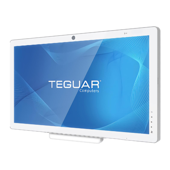
Description Front Camera (5M) RFID 23.8” true flat PCAP multi-touch Function keys: • Brightness up • Brightness down • Volume up • Volume down Touch Lock LED Indicator Light: • Batteries status • Power status Power button TM-5900-24 User Manual_V1.0... -
Page 17: Rear & Bottom View
Rear & Bottom View Item No. Description 75 x 75 VESA mounting holes 100 x 100 VESA mounting holes Cable door LED Indicator Light Camera Privacy Latch TM-5900-24 User Manual_V1.0... -
Page 18: I/O View
Item No. Description Battery Cover / Battery slot DC input USB 2.0(x2) USB 3.0(x2) Serial port 1 USB 2.0(x2) HDMI USB 3.0(x2) USB 3.0(x2) LAN1 LAN 2 Speaker BOX Power button HDD Cover / 2.5” HDD Slot TM-5900-24 User Manual_V1.0... -
Page 19: Dimension
Dimension Dimensions(W x D x H) : 581 x 351 x 44 mm TM-5900-24 User Manual_V1.0... -
Page 20: Basic Operation
NOTE: The system must be plugged into power adapter or battery charged before turning on for the first time. To turn off the system, power off the device safely using software “function that “shuts down computer” provide 12din the operating system. TM-5900-24 User Manual_V1.0... -
Page 21: Charging The Battery
Each battery provides a battery level indicator LED on the front of the system. The signal charge status are as follows: LED_1 (blue light) Power Status: No AC input (no light) PWRON_LED (constant light) Standby LED (flashing) LED_2 (orange light) Battery Status: Normal (no light) Charging (constant light) Low battery voltage (flashing) TM-5900-24 User Manual_V1.0... -
Page 22: System Assembly
Replacing the Battery Place the system face down, make sure not to scratch the screen. Replacing the HDD The system does not support hot-plug hard drives. Place the system face down, make sure not to scratch the screen. TM-5900-24 User Manual_V1.0... - Page 23 A 30-second countdown to Touch Lock will appear on the screen When there are 5 seconds left, there will be a warning sound to inform that the Touch Lock function will be terminated. Different alert sounds can be modified in the driver settings. TM-5900-24 User Manual_V1.0...
- Page 24 2. Install the speaker box audio cable on the audio jack of the speaker icon. 3. Install two M3 x10mm screws to fix the speaker box. Operation Caution We recommend that contacting your service contract to assemble and remove such parts. TM-5900-24 User Manual_V1.0...
-
Page 25: Specification
CAN/CSA-C22.2 No. 60601-1:14 (R2018) Medical electrical equipment Certification — Part 1: General requirements for basic safety and essential performance, Rev. November 2018 Operating Temperature 0°C ~ 35°C (32°F ~ 95°F) Storage/Transportation -20° ~ 60°C (-4°F ~ 140°F) TM-5900-24 User Manual_V1.0... - Page 26 Use only the following specification power cords: 18AWGmin., Type SJT, 125V/10A, UL or CSAl is ted, 3m max, hospital grade (if applicable for US/Canada market). In Europe and United Kingdom, the three-core power cord must be 3x0.75mm , Type H05VV-F, 250V/6A, VDE or BSI, 3m max. TM-5900-24 User Manual_V1.0...
-
Page 27: Bios Introduction
3) Use the “cd [folder path]” command to enter the directory where the update tool and BIOS files are store. After this, type the command “Fpt.efi /f [BIOS File Name] /bios” to update BIOS, where “/f” means flash the ROM, “/bios” means flash the BIOS region only. TM-5900-24 User Manual_V1.0... -
Page 28: Updating Bios Under Windows Environment
It is recommended that press “F3-Enter-F4-Enter”in BIOS Setup Utility to load defaults again. 7.1.3 Updating BIOS under Linux Environment Please refer to the update method under Windows. Administrator under Windows means that Linux Root privilege, command prompt corresponds to Linux Shell. TM-5900-24 User Manual_V1.0... -
Page 29: Intel Me Firmware Update
4) After the step 3), it goes to update BIOS. Do not reboot, turn off and disconnect power until screen shows green strings” FPT Operation Successful”. 5) Shut down and disconnect power source for several seconds, and restart the motherboard. The first-time power on, it will reboot for loading defaults and others TM-5900-24 User Manual_V1.0... -
Page 30: Updating Intel Me Firmware Under Linux Environment
Previous Values Optimized Defaults Save & Exit In the post interface, press to open the boot selection menu <Esc> Exit Save Changes Operation steps: 1) Press F4 to save the settings and exit in the BIOS Setup Utility. TM-5900-24 User Manual_V1.0... -
Page 31: Setting Date & Time
3) Enter the password you want to set again to make sure it is entered correctly. When you want to delete a user password, you should change the password by pressing carriage return directly in the Create New Password window to clear the password. TM-5900-24 User Manual_V1.0... -
Page 32: Set Up Power-On Self & Timed Power On
2) Set the item to “Enabled”. When the open-box detection cap is shorted, the chassis is considered to have been compromised. The post interface will prompt the chassis for intrusion alarms and the status TM-5900-24 User Manual_V1.0... -
Page 33: Instructions For The Display Settings
Legacy, and legacy boot items will be filtered when selected as UEFI. 7.12 Setting PXE Boot Open UEFI PXE: 1) Please select the “Advanced - Network Stack Configuration ”item; 2) Set Network Stack or UEFI PXE to Enabled; TM-5900-24 User Manual_V1.0... - Page 34 TM-5900-24 User Manual_V1.0...
-
Page 35: Description Of The Bios Options
Display the Total Memory ⚫ System Date Set the System Date. Date format is “month/day/year”. Use Tab to switch between Date elements. Make the modification by entering the number or pressing the “+/ -” key. Default Ranges: TM-5900-24 User Manual_V1.0... -
Page 36: Advanced
Power & Performance Power & Performance option ⚫ Trusted Computing Trusted Computing Settings ⚫ ACPI Settings ACPI(Advanced Configuration and Power Management Interface) Parameters ⚫ IT5571 Super IO Configuration System Super IO Chip Parameters ⚫ Display Configuration Display Configuration Parameters TM-5900-24 User Manual_V1.0... - Page 37 CSM (Compatibility Support Module) Configuration: Enable/Disable, Option ROM execution settings, etc. ⚫ NVMe Configuration NVMe Device Options Settings ⚫ Intel (R) Ethernet Controller (3) I225-V-00:A0:C9:00:00:00 Configure Gigabit Ethernet device parameters 7.13.2.1 CPU Configuration This menu contains the following information: ⚫ Type TM-5900-24 User Manual_V1.0...
- Page 38 Number of cords to enable in each processor package ⚫ BIST Enable/disable BIST (Built-In-Self Test) on reset ⚫ AP threads Idle Manner AP threads Idle Manner for waiting signal to run ⚫ Enable/disable AES (Advanced Encryption Standard) TM-5900-24 User Manual_V1.0...
- Page 39 The options after entering the interface settings above are as follows. RC6(Render Standby): Check to enable render standby support Maximum GT frequency : Maximum GT frequency limited by the user. Choose between 100MHZ and 1300MHZ. Value beyond the range will be clipped to min/max supported by SKU. TM-5900-24 User Manual_V1.0...
- Page 40 Enable or disable Endorsement Hierarchy ⚫ TPM 2.0 UEFI Spec Version Select the TCG2 Spec Version support. TCG_1_2: The compatible mode for Win8/Win10. TCG_2: Support new TCG_2 protocol and event format for Win10 or later. ⚫ Physical Presence Spec Version TM-5900-24 User Manual_V1.0...
- Page 41 Enable/Disable System ability to Hibernate (OS/S4 Sleep State). This option may not be effective with some operating systems. ⚫ ACPI Sleep State Select the highest ACPI sleep state the system will enter when the SUSPEND button is pressed. ⚫ S3 Video Repost Enable/Disable S3 Video Repost. TM-5900-24 User Manual_V1.0...
- Page 42 The options after entering the interface settings above are as follows. Serial Port: Enable/Disable Serial Port (COM) Device Settings: Display the Current Device Settings Change Settings: If the board supported, this menu shows. Select an optimal setting for Super IO Device. TM-5900-24 User Manual_V1.0...
- Page 43 7.13.2.6 Display Configuration This menu contains the following information: ⚫ LCD Panel Type it is used to change the built-in screen output resolution TM-5900-24 User Manual_V1.0...
- Page 44 This menu contains the following information: ⚫ SATA Controller(s) Enable/Disable SATA Device. ⚫ SATA Mode Selection Determine how SATA controller(s) operate. ⚫ Serial ATA Port X Display Serial ATA Port X Device Information ⚫ Port X Enable/Disable SATA Port X TM-5900-24 User Manual_V1.0...
- Page 45 This option allows select different settings: signal、+5V、+12V ⚫ COM1 Pin9 Selection This option allows select different settings: signal、+5V、+12V ⚫ COM2 Pin1 Selection This option allows select different settings: signal、+5V、+12V ⚫ COM2 Pin9 Selection This option allows select different settings: signal、+5V、+12V TM-5900-24 User Manual_V1.0...
- Page 46 Such as day: 2, hour: 13, minute:0, second:0, means 2nd of each month at 13 o'clock on the boot. When day is 0, it means that the point in time set every day is turned on. TM-5900-24 User Manual_V1.0...
- Page 47 Device power-up delay: Maximum time the device will take before it properly reports itself to the Host Controller. ‘Auto’ uses default value: for a Root port it is 100ms, for a Hub port the delay is taken from Hub descriptor. 7.13.2.11 Network Stack Configuration TM-5900-24 User Manual_V1.0...
- Page 48 Wait time in seconds to press ESC key to abort the PXE boot. Use either +/ - or numeric keys to set the value. ⚫ Media detect count Number of times the presence of media will be checked. Use either +/- or numeric keys to set the value. 7.13.2.12 CSM Configuration TM-5900-24 User Manual_V1.0...
- Page 49 Thisoptioncontrols Legacy/UEFI ROMs priority Option ROM execution ⚫ Network Controls the execution of UEFI and Legacy Network OpROM ⚫ Storage Control the execution of UEFI and Legacy StorageOpROM ⚫ Video Control the execution of UEFI and Legacy VideoOpROM TM-5900-24 User Manual_V1.0...
- Page 50 ⚫ Other PCI devices Determine OpROM execution policy for devices other than Network, Storage or Video 7.13.2.13 NVMe Configuration This menu contains the following information: ⚫ NVMe Configuration Display NVMe Device information TM-5900-24 User Manual_V1.0...
- Page 51 7.13.2.14 Intel(R) Ethernet Controller (3) I225-V This menu contains the following information: ⚫ Driver Information Display Driver Information, MAC address, Patent Information, etc. TM-5900-24 User Manual_V1.0...
-
Page 52: Chipset
7.14 Chipset This menu contains the following information: ⚫ System Agent(SA) Configuration System Agent (SA) Parameters ⚫ PCH-IO Configuration PCH Parameters TM-5900-24 User Manual_V1.0... -
Page 53: System Agent (Sa) Configuration
This menu contains the following information: ⚫ Memory Configuration Memory Configuration Parameters. ⚫ Graphics Configuration Graphics Configuration Settings ⚫ TCSS setup menu TCSS Configuration Settings ⚫ Display setup menu Display Configuration Settings ⚫ PCI Express Configuration PCI Express Configuration Settings ⚫ VT-d TM-5900-24 User Manual_V1.0... - Page 54 7.14.1.1 Memory configuration This menu contains the following information: ⚫ Display the Memory RC version, speed, Timings, etc. TM-5900-24 User Manual_V1.0...
- Page 55 Select the GTT Size ⚫ Aperture Size Select the Aperture Size\n\nNote : Above 4GB MMIO BIOS assignment is automatically enabled when selecting 2048MB aperture. To use this feature, please disable CSM Support ⚫ PSMI SUPPORT Enable or disable PSMI TM-5900-24 User Manual_V1.0...
- Page 56 Enable the ITBT PCIE on Extra Segment If disabled, all ITBT PCIE will be enumerated on segment0, if enabled, all ITBT PCIE will be enumerated on Segment1. ⚫ TCSS USB Configuration SA TCSS USB Configuration settings, default off. TM-5900-24 User Manual_V1.0...
- Page 57 7.14.1.4 Display setup menu This menu contains the following information: ⚫ DDI Port X Configuration DDI Port GPIO: disable or native DP-HDMI TM-5900-24 User Manual_V1.0...
- Page 58 Enable or disable ClockReq Messaging ⚫ PCI Express slot selection Select the PCIE M2 or CEMx4 slot ⚫ Enable RST GPIO Delay Enable or disable RST GPIO delay ⚫ PCI Express Root Port 1 Show the PCI Express Root Port Settings TM-5900-24 User Manual_V1.0...
-
Page 59: Pch-Io Configuration
7.14.2 PCH-IO Configuration This menu contains the following information: ⚫ PCI Express Configuration PCI Express Configuration settings. ⚫ USB Configuration USB Configuration settings. ⚫ HD Audio Configuration HD Audio Subsystem Configuration Settings. TM-5900-24 User Manual_V1.0... - Page 60 0th will become visible ⚫ PCIe EQ settings This form contains options for controlling PCIE EQ process ⚫ PCI Express Root Port 5 PCI Express Root Port Settings ⚫ PCI Express Root port 9 PCI Express Root Port Settings TM-5900-24 User Manual_V1.0...
- Page 61 Select 'Enabled' if Overcurrent functionality is used. Enabling this will make xHCI controller consume the Overcurrent mapping data ⚫ USB Port Disable Override Selectively Enable/Disable the corresponding USB port from reporting a Device Connection to the controller. TM-5900-24 User Manual_V1.0...
- Page 62 7.14.2.3 HD Audio Configuration This menu contains the following information: ⚫ HD Audio Control Detection of the HD-Audio device. Disabled = HDA will be unconditionally disabled. Enabled = HDA will be unconditionally enabled. TM-5900-24 User Manual_V1.0...
-
Page 63: Security
7.15 Security This menu contains the following information: ⚫ Administrator Password Set Administrator Password ⚫ User Password Set User Password Secure Boot ⚫ TM-5900-24 User Manual_V1.0... -
Page 64: Boot
Has no effect for BBS boot options. ⚫ Boot Mode Select Select boot mode Legacy/UEFI ⚫ FIXED BOOT ORDER Priorities Display Boot order, and allow to set Hard Drive/USB/XXX boot order in this group TM-5900-24 User Manual_V1.0... -
Page 65: Save& Exit
Save as User Defaults Save the changes done so far as User Defaults. ⚫ Restore User Defaults Restore the User Defaults to all the setup options. Boot Override ⚫ UEFI: Built-in EFI shell Launch BIOS Built-in UEFI Shell TM-5900-24 User Manual_V1.0...
Need help?
Do you have a question about the TM-5900-24 and is the answer not in the manual?
Questions and answers