Table of Contents
Advertisement
Quick Links
Advertisement
Table of Contents

Subscribe to Our Youtube Channel
Summary of Contents for HuddleCamHD HC-JOY-G4
- Page 1 Model No. HC-JOY-G4 V1.0 (English) Please check huddlecamhd.com for the most up to date version of this document. 152 Robbins Rd., Downingtown, PA 19335 USA | HuddleCamHD.com | 484-593-2247 ver 1_0 rev 2-23 ©2023 | HuddleCamHD | All Rights Reserved...
-
Page 2: Table Of Contents
Table of Contents Preface . . . . . . . . . . . . . . . . . . . . . . . . . . . . . . . . . . . . . . . . . . . . . . . . . . . . . . . . . . Precautions . -
Page 3: Preface
Joystick . Prior to installation and usage, please read the manual thoroughly . Precautions To avoid any damage to the unit, please take these precautions when using your HC-JOY-G4 Joystick Controller . •... -
Page 4: Warranty
Copyright Notice The entire contents of this manual / guide, whose copyright belongs to HuddleCamHD, may not be cloned, copied, or translated in any way without the explicit permission of the company. The product specifications referred to in this document are for reference only and as such are subject to updating at any time without prior notice. -
Page 5: Physical Description
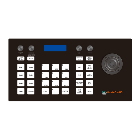
Physical Description 11 12 1. Speed Control Dial 8. Focus Control Adjust Control Speeds Adjust or Lock Focus 2. Mode Change Button 9. Camera Select Basic & Matrix Modes Select your camera 3. LCD Display 10. Numeric Buttons Displays Connection Info Used for Presets 4. -
Page 6: Back View Of The Joystick Controller
Back View of the Joystick Controller 1 . RS-232 Port (DB9 connection) 2 . RS-422 Port 3 . 12V DC Power Port 4 . Power Switch 5 . Grounding Knob ver 1_0 rev 2-23... -
Page 7: Key Product Features
Key Product Features • All Metal housing • VISCA, PELCO-D and PELCO-P protocol support • Key-press “BEEP” confirmation (optional – set on or off) • Variable speed control of pan, tilt, zoom, focus, and presets • Auto/Manual Focus and Iris •... -
Page 8: Installation
Installation • Power Supply Interface (5.5mm x 12mm center pin JEITA style jack): 12VDC / 2000mA power supply • RS485/422 interface (5p screw terminal): Ŝ 1:485+/422TxA Ŝ 2:485-/422TxB Ŝ 3:422RxA Ŝ 4:422RxB Ŝ 5:485/422Gnd • RS232 interface (DB9M port): 2:Rx, 3:Tx, 5:Gnd Hardware Features •... -
Page 9: Keyboard/Joystick Operation
Keyboard/Joystick Operation Basic Control • Pan & Tilt Control Ŝ Joystick movement provides variable speed pan and tilt of the camera head . • Zoom Control Ŝ Rotation of the joystick controls variable speed zoom of the lens . ▪ Clockwise rotation of the joystick = zoom in . -
Page 10: Selecting A Camera
3 . Press the Enter buttonave “Call” mode, press the “Esc” key . Notes on using presets with VISCA: For your convenience, the HC-JOY-G4 uses the same presets as the IR remote controller, VISCA, Pelco-D, or Pelco-P protocols. This is in contrast to Sony’s traditional offset of 1 between the IR remote and VISCA commands . -
Page 11: Joystick Setup Menu - Lcd Menu
Joystick Setup Menu - LCD Menu Key Tone • Options include: On, Off Restore Default • You must press Enter twice to restore the default settings . Press the Escape button to cancel . ADD: • Options include: VISCA, Pelco-D, Pelco-P •... -
Page 12: Keyboard/Joystick Connection Wiring And Indicators
Keyboard/Joystick Connection Wiring and Indicators RS-232 DB9 Camera Mini DIN RS422 RS422 Joystick Power: • Keyboard/Joystick requires external 12VDC . Use only the 12VDC power supply shipped with the unit . The Keyboard/Joystick may be connected to cameras via RS-232, RS-485 or RS-422 . •... - Page 13 • For RS-485, connect the 5p screw terminal port of the KB to the RS-485 port of the camera with pin-out as follows: Ŝ KB Ta – Pin 1---------- Camera (+) Ŝ KB Tb – Pin 2---------- Camera (-) Ŝ KB Gnd – Pin 5---------- Camera (G) (if present – some cameras will not require a G) •...
-
Page 14: Troubleshooting
VISCA-out port of first camera to VISCA-in port of next camera, etc . . . A VISCA cross-over cable must be used for all camera to camera connections . These are available from HuddleCamHD in various lengths as well as from other sources .
Need help?
Do you have a question about the HC-JOY-G4 and is the answer not in the manual?
Questions and answers