Table of Contents
Advertisement
Quick Links
Advertisement
Table of Contents

Subscribe to Our Youtube Channel
Related Manuals for Schelde Sports Super SAM 325 PRO

Summary of Contents for Schelde Sports Super SAM 325 PRO
- Page 1 Manual Super SAM 325 PRO 1612200...
-
Page 2: Our 5X5 Range
SAM 225 Club SAM 165 Club Little SAM Pro SAM School ABOUT THIS MANUAL This documentation was originally prepared in Dutch by JF Operations. Handleiding Super SAM 325 Pro Manual: 30-06-2021 Date: © Copyright: JF Operations, Helmond, 2021 No part of this documentation may be reproduced in any form without permission of JF Operations. -
Page 3: Table Of Contents
SAFETY INTRODUCTION SAFETY RULES USERS UNIT AND PARTS DISPOSAL OF THE UNIT SOCIAL RESPONSIBILITY CHECKLIST SUPER SAM 325 PRO CERTIFICATION PACKAGING, WEIGHT AND SIZES INSTALLATION OPERATING INSTRUCTIONS OPERATING INSTRUCTIONS FOR USE WITH MANUAL DSF/APF OPTION ADJUSTING THE SPRING PACKAGE OPTIONAL FITTINGS MAINTENANCE www.scheldesports.com... -
Page 4: Dear Customer
DEAR CUSTOMER Work that must be carried out by the manufacturer’s personnel is not included in this documentation. This user manual has been prepared for anyone who wishes to use our apparatus and/or sports and games materials. This manual describes how to use and maintain the equipment in a responsible manner. -
Page 5: Introduction
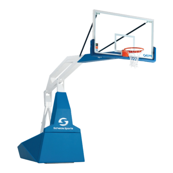
INTRODUCTION PURPOSE AND FUNCTION OF THE DEVICE The Super SAM 325 Pro is the worldwide standard for excellence. Designed and made by the inventors of the original SAM (Spring Assisted Mechanism) and DSF (Dynamic Sub Frame). The diamond-shaped safety padding gives this backstop a unique look. In addition, the cables are routed through the top beam. -
Page 6: Users
Do not remove the transport bracket before assembling the backboard. Removing the transport bracket without the backboard in place can cause serious accidents. The springs are under great tension. Keep the transport bracket and attachment hardware at hand. The backboard is made of tempered glass, exercise great caution! USERS Setting up and storing the unit may only be carried out by competent adult persons, who know and follow the rules of the Safety and Operating instructions. -
Page 7: Social Responsibility
Through these efforts and activities, they want to offer opportunities to children in countries who have little or no sports and games facilities at their disposal. This way we re-use our (gymnastic) equipment and sports and games materials and we work with less environmental impact. CHECKLIST SUPER SAM 325 PRO INCLUDED: - Backboard - Automatic lock on telescopic rod - Pro 180°... -
Page 8: Certification
CERTIFICATION The Super SAM 325 PRO has been FIBA certified for top level (level 1 and level 2) competitions and complies with the European standard EN1270:2005 Playing field equipment. Basketball equipment. Functional and safety requirements, test methods. Valid until 31 December 2021... -
Page 9: Packaging, Weight And Sizes
PACKAGING, WEIGHT AND SIZES PACKAGE 1 Portable basketball goal PACKAGE 2-A Tempered glass backboard PACKAGE 2-B Backboard padding PACKAGE 3 Dunk ring + net PACKAGE 4 Set of side paddings left/right www.scheldesports.com... - Page 10 PACKAGE 5-A Neck padding PACKAGE 5-B Base padding PACKAGE 6 Braces + tongues, hinges and fasteners for padding + chain for connecting the unit to the floor with safety hooks and accessory for the assembly of the glass backboard. PACKAGE 7 Optional manual DSF feature (APF) PACKAGE 8 Beam padding...
-
Page 11: Installation
INSTALLATION Assembly portable basketball backstop: • DO NOT EVER REMOVE THE TRANSPORT BRACE WITHOUT THE BACKBOARD BEING Warning MOUNTED ONTO THE BEAM! • Backboard, ring, net and padding may only The springs are under big tension. The be installed by qualified technical staff. weight of the backboard compensates •... - Page 12 STEP 5 Firmly tighten all bolts and nuts. Remove the temporary support. Installing backboard braces: STEP 6 Mount the M12 adjustor forks and fixing plates to the top corners of the backboard using 2 carriage bolts M10x30 with lockring aand spring washer. Centre the mounting plate with the slotted holes of the backboard frame and tighten the nuts.
- Page 13 STEP 9 Important : mount backboard perpendicular to the main beam. After correct horizontal adjustment, firmly tighten all bolts and nuts of ring and backboard onto the beam mounting plate. STEP 10 Mount cover plate back on the pressure release mechanism compartment of ring.
- Page 14 Installing the side pads to the base frame STEP 13 Install the mounting brackets (4 lugs supplied with M8x25 bolts, lock rings and spring washers) in the positions indicated at the rear of the padding panels, and then slide the side pads in the frame slots provided.
- Page 15 Installing the neck pad: STEP 16 Stick the included velcro strips 2 cm measured from the top of the beam on both sides. Now the neck pad can be added. Installing padlocks: STEP 17 Installing the 2 padlocks: Install the first padlock on the rear lock. Mount the second padlock to the locking pin of the telescope.
- Page 16 Installing/adjusting the dynamic sub frame STEP 18 Position the DSF frame under the front of the base frame, whereby the sockets line up perfectly with the vertical rods at either side of the front. Gently lift the backstop to its game position, whereby the rods slide into the DSF sockets.
-
Page 17: Operating Instructions
OPERATING INSTRUCTIONS STEP 1 Check if floor is free of debris, obstacles etc prior to moving the backstop, in order to avoid damage to the wheels. STEP 2 Move (push from the rear or pull from the ring) the folded backstop to the position desired. IMPORTANT : ALWAYS MOVE THE UNIT FIRST IN THE DIRECTION (POSITION) OF THE SWIVEL WHEELS, THEN STEER THE UNIT ONCE IT IS IN MOTION... - Page 18 STEP 4-B Connect the two side eyebolts of the base frame to the floor anchors using the chains and D-locks provided. DO NOT FULLY TIGHTEN THE CHAIN BUT LEAVE IT JUST A LITTLE BIT SLACK, this will avoid vibrations in the unit after heavy dunks. (this option is available in case rear anchoring is not possible;...
- Page 19 STEP 8 After the automatic lock pin has snapped into place, insert the pin and install the padlock. Turn the star-knob clockwise. STEP 9 Use the height adjuster at the rear of the base frame for fine tuning of ring height, if necessary. www.scheldesports.com...
-
Page 20: Operating Instructions For Use With Manual Dsf/Apf Option
OPERATING INSTRUCTIONS FOR USE WITH MANUAL DSF/APF OPTION STEP 1 Check, when the SAM unit is in storage position, the position of the sliding bracket: Pulled out = automatic operation Pulled in = manual operation STEP 2 Make sure the sliding bracket is pulled in, to avoid the DSF or APF system from lowering automatically when you raise the main beam of the SAM unit into playing position. - Page 21 STEP 5 Push down, simultaneously with 2 persons, both the left and right operating bars down. By pushing down the bars, the front wheels of the SAM unit will lift off the floor and the front of the unit will support on the DSF or APF systems.
- Page 22 ADJUSTING THE SPRING TENSION After a certain period of use, the tension of the springs may have decreased to the point of making it difficult to smoothly lower / raise the backstop. In this case the tension of the springs must be increased, in order to avoid damage to the unit.
-
Page 23: Adjusting The Spring Package
ADJUSTING THE SPRING PACKAGE Adding a spring The Super SAM 325 Pro has a provision for inserting an extra spring (if a shot clock is mounted on the beam, this extra spring will be mandatory for a smooth folding cycle).
Need help?
Do you have a question about the Super SAM 325 PRO and is the answer not in the manual?
Questions and answers