
Summary of Contents for Plum ecoLAMBDA
- Page 1 MODULE ecoLAMBDA ver.2 TO OPERATE THE LAMBDA PROBE INSTALLATION MANUAL ISSUE: 1.0_EN 02-2021...
- Page 2 ELECTRIC DEVICE UNDER VOLTAGE! Before any action related to the power supply (cables connection, installation, etc.) check if the controller is not connected to the mains! Installation should be done by a person with appropriate electrical qualifications. Improper cables connection could result in damage to the controller.
-
Page 3: Table Of Contents
TABLE OF CONTENTS SAFETY ............4 GENERAL INFORMATION ......4 DIRECTIVE WEEE 2012/19/EU ..... 4 TECHNCIAL DATA ........5 SET CONTENTS........... 5 MOUNTING THE MODULE ......5 6.1. Installation and use of Lambda probe ..5 6.2. Module installation ....... 7 6.2.1. -
Page 4: Safety
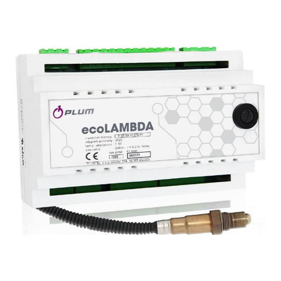
2. GENERAL INFORMATION the environment and human health. ecoLAMBDA ver. 2 module is used for measuring the oxygen content in exhaust fumes. The measurement results are sent via RS485... -
Page 5: Techncial Data
0,6 kg Pipe Dimensions 140 mm x 90 mm x 65 mm Proper position 5. SET CONTENTS - ecoLAMBDA ver.2 module 1 pc - NGK Lambda probe 1 pc - Module installation manual 1 pc - Transmission cable with connectors 1 pc 6. - Page 6 Caution for risk of burns. The probe’s tip connected to the module may reach a temperature of several hundred ºC. Recommended shape of probe’s connection nozzle. Maximum acceptable operating temperatures of NGK Lambda probe: 600°C – for the probe and its metal parts, ...
-
Page 7: Module Installation
The range of permissible cross-sectional areas to connect terminals is 6.2. Module installation presented in the table below: The ecoLAMBDA ver.2 module is designed for Cable cross- Circuit type enclosure. A standard installation housing can section be used for enclosure of eight modules. -
Page 8: Fuse Replacement
Connection of module to Lambda probe should be made in accordance to the below table and electrical diagram. Terminal Designation Wire color Probe type: NGK ZFAS-U2 Grey Black White Brown Blue 7. FUSE REPLACEMENT Before replacing the fuse disconnect the mains supply from the module. The mains fuse is located inside the module housing on electrical board. -
Page 9: Electrical Scheme
8. ELECTRICAL SCHEME Electrical wiring diagram of the module: FU – fuse (1,25 A / 250 VAC), ecoMAX – the main controller, NGK – Lambda probe type ZFAS-U2, RS485 – transmission (D+, D-), ! – connect only with two wires (do not connect with four wires, because of risk to damage the controller). Changes register: The manufacturer reserves the right to make design and software... - Page 12 Wspólna 19, Ignatki 16-001 Kleosin Poland plum@plum.pl www.plum.pl National Waste Database No. 000009381...
Need help?
Do you have a question about the ecoLAMBDA and is the answer not in the manual?
Questions and answers