Table of Contents
Advertisement
Quick Links
Advertisement
Table of Contents

Summary of Contents for JG Maker Artist-D
- Page 2 Preface This is the user manual for the Artist-D 3D Printer. We recommend that you read this user manual thoroughly and understand the information, prior to operating the Artist-D 3D Printer. The user manual contains important instructions and information about how to use the printer in a safe and skilled manner.
-
Page 3: Product Introduction
【4】Do not put your hands into the printing box during the printing, to avoid physical injury. 【5】Use the filaments recommended by the manufacturer so as to avoid clogs in the hot end, or damages to the printer. 【6】Do not use any other power cable, other than the one supplied. Use a grounded power outlet. -
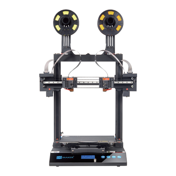
Page 4: Product Overview
Power requirements: AC 110/220 Volts Build size: 300*300*340mm Dimension: 560*640*630mm Build surface: FA specially made platform Net weight: 15kg Control panel: LCD display + Control dial Shipping dimension:680*670*320mm Connectivity: SD card Shipping weight: 21kg Supported file types: STL、OBJ、G-Code Supported OS:Windows7/Windows10/XP Software: Cura/JGcreat (64 bit)... -
Page 5: What's Included
What's included Main body Brush box Base Gantry Spool holder Idler Accessories & Components Artist-D User Manual Version: A2 Power cord USB cable Filaments Nozzle &Telfon User Manual Pliers Allen wrench Scraper Screws Filament sample Warranty card PET leveling tape T-shaped Allen key Wrench 8~10 SD card &... -
Page 6: Assembly Process
Assembly Process Install the gantry onto the base. Remove the parts from the box. Note that the base and gantry units are preassembled at the factory. Put the gantry noto the base, and make sure the gantry bottom is properly inserted in the base slot to ensure the stability of the frame. - Page 7 Install the gantry onto the base Attach the spindle to a spool holder using the screw provided. Attach the spool holder to the top of gantry with two thumb screws. Repeat the process to install the other spool holder. Note: Threaded holes for thumb screws are located on the gantry at the positions shown.
-
Page 8: Cable Connection
Cable Connection Plug in the cables The cables are provided with labels. Observe these, and the type of connectors for proper identification.Plug the cables into correct socket, being careful not to bend the pins on the connectors. Note: We highly recommend you to take a photo of the connector settings for future refer- ence. -
Page 9: Screen Information
Screen Information Selected Temperature fo Nozzle 2 Current Temperature fo Nozzle 2 Selected Temperature of Bed Selected Temperature fo Nozzle 1 Parts Cooling Fan Indicator Current Temperature fo Nozzle 1 Current Temperature of Bed X/Y/Z Axis Position Print Speed Print Progress Indicator Status Message Control Knob >PRESS:... -
Page 10: Bed Leveling
Bed leveling The bed has been leveled at the factory, but after shipping and assembly, you may need to level it again by following these steps: Home X, Y, and Z axes: Press and rotate the control knob to select: Motion >... -
Page 11: Filament Loading
Note: The E2 height canbe adjusted a little up or down when there is needed. Note to loose the four screws around, then to rotate the spring bolt to adjust the E2 height. Filament loading Heat the nozzle: Press and rotate the Control knob to Prepare >Preheat PLA >Preheat PLA to heat the nozzle according to the temperature range of the filament you are going to use.
Need help?
Do you have a question about the Maker Artist-D and is the answer not in the manual?
Questions and answers