Table of Contents
Advertisement
Quick Links
IST-300 - User manual
2 channel portable function generator
Manual version
Date
Hardware version
ISTEC INTERNATIONAL BV
Netherlands:
Istec International BV
Meer en Duin 8
|
www.istec.com
NL – 2163 HA Lisse
+31 (0)252 433 400
mail@istec.com
2.0
22-7-2019
IST-300-VC-V02
Belgium:
Istec International BVBA
Zendelstraat 6
BE – 3680 Opoeteren
+32 (0)89 303 204
mail@istec.com
Advertisement
Table of Contents

Summary of Contents for ISTEC IST-300
- Page 1 IST-300 - User manual 2 channel portable function generator Manual version Date 22-7-2019 Hardware version IST-300-VC-V02 Netherlands: Belgium: Istec International BV Istec International BVBA Meer en Duin 8 Zendelstraat 6 ISTEC INTERNATIONAL BV www.istec.com NL – 2163 HA Lisse BE – 3680 Opoeteren...
-
Page 2: Table Of Contents
A portable vibration calibrator ........................3 A user-friendly hardware interface ......................4 2.1. Front panel ............................4 2.2. Top Panel ............................5 Using the IST-300..............................6 3.1. Turn on the device ........................6 3.2. Connect the output ........................6 3.3. -
Page 3: A Portable Vibration Calibrator
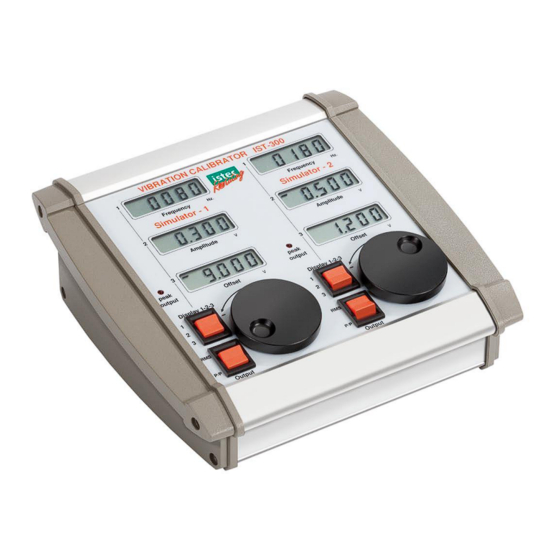
1. A portable vibration calibrator The IST-300 is portable vibration signal simulator to simulate axial displacement, acceleration and velocity vibration signals (2oo2 testing). The 2- channel vibration calibrator sends out a pure sine wave with a programmable amplitude, frequency and offset. Signals can either be send through field wiring or directly to the vibration protection system. -
Page 4: A User-Friendly Hardware Interface
Display switch – To toggle between the LCD displays for setting the right values ▪ ▪ Output switch – To toggle between RMS or peak-to-peak ▪ Incremental rotary knob – For adjusting the values of the LCD displays Figure 2 – Hardware interface Istec International BV | www.istec.com 4 / 10... -
Page 5: Top Panel
▪ One BNC output per channel (50 Ohm) – To connect the output to the device to be tested Power input socket – To connect the adapter for charging the battery ▪ Istec International BV | www.istec.com 5 / 10... -
Page 6: Using The Ist-300
3. Using the IST-300 To use the IST-300 either the batteries need to be charged or the unit needs to be connected to the power adapter. The interface is very user-friendly and identical for both channels. 3.1. Turn on the device After turning on the IST-300 by toggling the power switch, several data is shown on the LCD displays. -
Page 7: Combined Output
▪ Range: 0 mV … 19.000 mV or 0 mV … -19.000 mV When the polarity switch on the top of the IST-300 is set to negative the output is a negative voltage. (see 3.4) E.g. required for Eddy Current Probe loops using -24 volt power. -
Page 8: Clipping
15.295 mV DC + (2.625 mV RMS * 1,414) = 19.007 m Volt Note: The factor 1,414 is the square root of two (√2) which is the difference between the RMS and Peak value for pure sinus shaped signals. Istec International BV | www.istec.com 8 / 10... -
Page 9: Specifications
C … 55 Storage @95% humidity: C … +80 C with batteries removed Battery: ReCyko+ battery Holds power up to 90% after 1 year ▪ >8 hour continuously ▪ Rechargeable: NI-MH fast charge ▪ Istec International BV | www.istec.com 9 / 10... -
Page 10: Declaration Of Conformity
5. Declaration of conformity Istec International BV | www.istec.com 10 / 10...
Need help?
Do you have a question about the IST-300 and is the answer not in the manual?
Questions and answers