
Summary of Contents for EverAccess EFM-AL-1A
- Page 1 Volume EverAccess User Manual...
- Page 2 E V E R F O C U S E L E C T R O N I C S C O R P O R A T I O N EFM-AL-1A Instruction Guide © 2004 Everfocus Electronics Corp 1801 Highland Ave Duarte CA 91010 Phone 626.844.8888 •...
-
Page 3: Table Of Contents
Table of Contents CHAPTER 1 Product Overview Features Parts List Specifications CHAPTER 2 Installing an Alarm Module into the Controller CHAPTER 3 Terminal/LED Definitions Alarm Module Terminal Definition Alarm Module LED Definition CHAPTER 4 Wiring Connection to Alarm Input Connection to Alarm Output Notes... -
Page 4: Product Overview
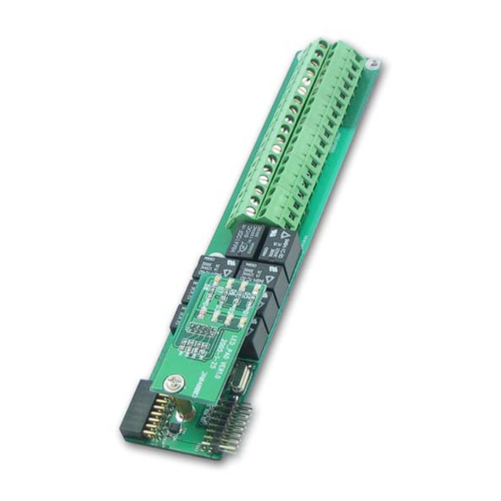
The alarm module (part number EFM-AL-1A) is the alarm expansion unit for the Flex Series Controller. The alarm module provides 8 alarm inputs and 8 alarm outputs. With the expansion alarm module and 4 door modules installed, the EverAccess Flex Series controller can support up to 10 alarm inputs and 18 alarm outputs. -
Page 5: Specifications
In addition, the following EverAccess products are required for use with the door module to achieve the correct functionality: EverAccess Flex Series Controller (part number EFC-02-1A) Specifications Items Parameter Input 8 alarm inputs Relay output 8 alarm outputs Power supply... -
Page 6: Installing An Alarm Module Into The Controller
Installing an Alarm Module into the Controller The EverAccess Flex series controller can accommodate up to 4 door modules and 1 alarm module. The alarm module connects to the door modules in a cascading fashion. It can be installed in any of the 5 available positions; the order of installation of the door modules and alarm module does not affect the functionality. -
Page 7: Terminal/Led Definitions
Chapter Terminal/LED Definitions The definitions of the module terminals are presented in this chapter. Alarm Module Terminal Definition There are 36 terminals on the alarm module. The positions and indexes are described in Fig 3.1. The definitions are described in Table 3.1. Fig. -
Page 8: Alarm Module Led Definition
4 Alarm3_In Alarm signal input 3 22 Alarm7_In Alarm signal input 7 5 GND 23 GND 6 Alarm4_In Alarm signal input 4 24 Alarm8_In Alarm signal input 8 7 Alarm1_NO Alarm 1 output for normally-open 25 Alarm5_NO Alarm 5 output for normally-open 8 Alarm1_COM Alarm 1 output in common 26 Alarm5_COM Alarm 5 output in common 9 Alarm1_NC... -
Page 9: Wiring
Chapter Wiring This chapter will describe, in detail, how to wire the terminals in the door modules. Connection to Alarm Input The alarm signals other than the fire alarm and alarm input 0 are controlled by the alarm module, which contains 8 alarm inputs and 8 alarm outputs. Using the 5 channel alarm signal input as an example, the method to connect the alarm module to the alarm sensor is shown in Fig. - Page 10 N.O. termina Exteral Alarm C.terminal Device Alarm module Fig. 4. 2 Normally open connection for alarm output 5 C.terminal Exteral Alarming N.C. terminal Device N.C. Alarm module Fig. 4. 3 Normally closed connection for alarm output 5...
-
Page 11: Notes
Notes... - Page 12 Room 609,Technology Trade Building. 91010 ,U.S.A Shangdi Information Industry Base, :+ 1-626-844-8888 Haidian District,Beijing China :+ 1-626-844-8838 :+ 86-10-62971096 :+ 86-10-62971423 Japan Office 1809 WBG Marive East 18F, 2-6 Nakase, Mihama-ku, Chiba city 261-7118, Japan : + 81-43-212-8188 : + 81-43-297-0081 EverAccess...
Need help?
Do you have a question about the EFM-AL-1A and is the answer not in the manual?
Questions and answers