Advertisement
Quick Links
FEATURES
•
Precision Laser Cut Parts
•
Lightweight Strong Airframe
•
Excellent Low Speed Stability
•
Comprehensive Instruction Manual
•
High Quality Balsa, Ply and Depron Parts
•
Excellent Precise Handling Characteristics
•
High Quality Comprehensive Hardware Pack
Instruction Manual
0
Advertisement

Summary of Contents for evolution models FUSION3
- Page 1 Instruction Manual FEATURES • Precision Laser Cut Parts • Lightweight Strong Airframe • Excellent Low Speed Stability • Comprehensive Instruction Manual • High Quality Balsa, Ply and Depron Parts • Excellent Precise Handling Characteristics • High Quality Comprehensive Hardware Pack...
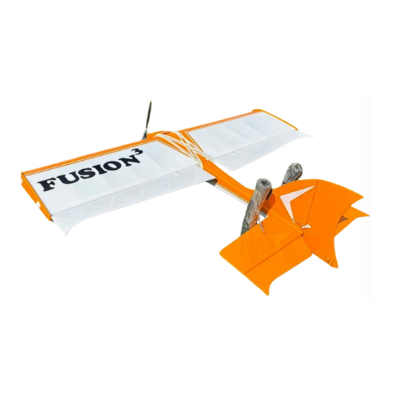
- Page 2 Introduction Evolution Models released the first Fusion in 2008, the Fusion I was designed with many years of Fun Fly experience. We would like to take this opportunity to thank all those that have supported us over the last 15 years.
-
Page 3: Hardware Pack
Enjoy. Building is part of aero modelling! This radio-controlled model is not a toy. It can cause serious injury to the operator, public and property if misused or abused. Ensure that you read all the instructions supplied with this kit and instructions provided with the engine/motor and radio control system or any other components purchased separately carefully. - Page 4 Fusion III Part List Laser Cut Sheets Some parts may be relocated on sheets without notice, please make sure you locate each part carefully...
- Page 5 Part No. Description Sheet Material Fin Base 6mm (1/4”) Balsa Fin / Tailplane Interface 6mm (1/4”) Balsa Fin Leading Edge (LE) 6mm (1/4”) Balsa Fin Trailing Edge (TE) 6mm (1/4”) Balsa Rudder LE 6mm (1/4”) Balsa Fin top 6mm (1/4”) Balsa Fin Base 6mm (1/4”) Balsa Fin TE...
- Page 6 Fusion Parts List Piano Wire U/C Front Leg 10 swg Rear Leg 10 swg Supports 10 swg Tail Skid 16 swg Description Quantity Undercarriage Front Leg Undercarriage Rear Leg Undercarriage Support Tail Skid...
-
Page 7: Building Instructions
Building Instructions The laser is set to the minimum setting to minimise any ‘V’ cut in the balsa, please check and run a knife through any areas that require releasing and the tabs that hold the part in the sheet. Fin and Rudder Take the three parts that form the Fin and Rudder (Parts 1, 1a, 2, 3, 4, 5, 6, 7 and 15(2)), trial fit before gluing together. - Page 8 Tail Plane and Elevator Take the pre-cut parts (Parts 8, 9, 10(2), 11, 12(2), 13(2), 14(2), 14a(2) and 15(4)) which form the Tail Plane and Elevator, trial fit, ensure the tips are at 90° to the leading and trailing edge before gluing. With the supplied strip of 6 x 9.5mm (1/4”...
- Page 9 When test fitting the above parts to the fuselage a notch will be required in the rudder there the wire joiner passes through. Make sure the notch is big enough to allow full movement of the rudder. Shape all parts to a smooth Finish and round off the leading edge of the Tail Plane ready for covering.
- Page 10 into the back (inside the fuselage). We suggest gluing the nuts in place to prevent them falling out when installing the bolts. F1 should be placed with the three wire holes set towards the bottom of the Fuselage. With F1 and F2 in place the Fuselage sides should taper back, the gap should be approximately 25mm and the sides should remain straight.
- Page 11 Plank the bottom of the hatch floor with 3mm (1/8”) balsa except for the tab Test fit the hatch latch by drilling a hole in the rear edge of the U/C plate as shown above. Cut the inner bush to allow the latch to swing with resistance once the screw is fully seated.
- Page 12 The webbing should sit on the front of the spars, do not glue in place now, just use as a guide for rib spacing. Carefully cut the ribs from the Depron sheet. Dimensions shown in mm Pin the main and trailing edge spars 6mm x 6mm x 1220mm (¼” x ¼” x 48”) to the surface. Use a straight edge to ensure that it is completely straight and both parts are parallel.
- Page 13 Continue to place the ribs, do not glue W4A at this stage. W4A is glued once the sheeting has been completed and covers the whole of the wing end. Ensure that you place the correct rib in the correct position as per the diagram above. Once dry, place the upper spar into position and glue in place.
- Page 14 Un-pin from the board and repeat the sheeting process to the underside of the wing. Once completed cut off any excess spar, leading, trailing edge and sheeting, leave flush with the end depron ribs Before installing W4a install the supplied captive nuts so when fitted they are on the inside of the wing.
- Page 15 Shape the leading edge as step 4 on page 13, continually checking the fit to the Fuselage. Make up the wing tips/fences using parts 34 and 35 making sure to make a left- and right-hand pair. Part 35 fits against W4a and Part 34 (the outer rim) slides over the wing as shown below. The wing tips are removeable and installed using the supplied M3 x 10mm hex bolt and washer.
- Page 16 Repeat the above stages for the second aileron. Ensure that you get at least 45° free movement either way. Do not glue the hinges in at this stage! Cover both parts with your chosen covering first. Shape to provide a smooth, blemish free surface ready for covering. Covering Before covering, seat the wing, Tail Plane and Fin and make sure that all fit.
- Page 17 Fits best fit, make minor adjustments as before. Bind and solder as before. Repeat for the second side, ensuring that the supports are positioned symmetrically. Once the Fuselage has been covered, line the undercarriage up with the centre of the two mounting plates.
- Page 18 repeat the gluing process. Repeat this for the second aileron. Due to the large control surfaces we would recommend pinning the hinges. This is left to the builder’s discretion. Install the servos into the wing and feed the wires through the tubes. Pull the wires out at the centre section where the sheeting was cut earlier.
- Page 19 Re-insert the Fin and make sure that the cut-out in the base of the Fin lines up with the Tail Plane slot. Insert the Tail Plane to confirm. One satisfied with the fit, glue the Fin into position applying glue on the base where it joins to the Tail skid and at the junction with the top deck. Ensure that the Fin is vertical, with the wing seated;...
- Page 20 Elevator closed loop cable will be placed centrally on the rear deck but needs to be inserted at an angle so that the cable can be run past the Fin post. Make up the closed loop systems to the Elevator and Rudder as shown below. Ensure the crimps hold the wire tightly, place a drop of Cyano to make sure the wires cannot move.
- Page 21 gravity is achieved ensure that the battery is unable to move during flight or foul the servos. In the prototype models the battery is held in with foam glued to the side of the fuselage, however the fixing is left to the builders discretion. Receiver and Battery Position The battery and receiver are to be located between the servo tray and tank or flight battery.
- Page 22 Also make sure that any parts bought separately are suitable for their application. Evolution Models do not have any control over the final assembly of the model or material used for final assembly. No liability shall be assumed for damage resulting from the use of this product. By the act of using the Final assembled product the user accepts all resulting liability.
- Page 23 This disclaimer does not limit or reduce Evolution Models’ liability for death or personal injury caused by Evolution Models’ negligence.
Need help?
Do you have a question about the FUSION3 and is the answer not in the manual?
Questions and answers