Sign In
Upload
Download
Table of Contents
Contents
Add to my manuals
Delete from my manuals
Share
URL of this page:
HTML Link:
Bookmark this page
Add
Manual will be automatically added to "My Manuals"
Print this page
×
Bookmark added
×
Added to my manuals
Manuals
Brands
Farm King Manuals
Lawn Mower
RSB6
Operator and parts manual
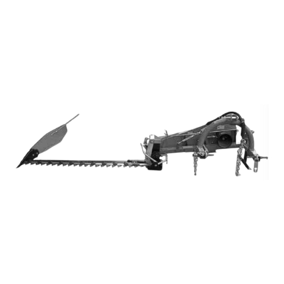
Farm King RSB6 Operator And Parts Manual
Sickle bar mower
Hide thumbs
1
2
Table Of Contents
3
4
5
6
7
8
9
10
11
12
13
14
15
16
17
18
19
20
21
22
23
24
25
26
27
28
29
30
31
32
33
34
35
36
37
38
39
40
41
42
43
44
45
46
47
48
page
of
48
Go
/
48
Contents
Table of Contents
Bookmarks
Table of Contents
Table of Contents
Introduction
Safety
Safety Instructions
Safety Warning Decals
Decal and Sign Locations
Specifications
Main Features
Technical Specifications
Standard Equipment
Assembly
Blade Assembly
Attaching the Sickle Bar Mower to the Tractor
Tractor Linkage
Tractor Linkage of Sickle Bar Mower with Mechanical Lift
Tractor Linkage of Sickle Bar Mower with Hydraulic Lift
Hydraulic Kit Assembly Instructions
Operation
Cutting Speed
Safety Release Breakaway Latch
Cutting Height Adjustment
Raising and Lowering of Sickle Bar Mower Blade
Working Position
Unhitching the Sickle Bar Mower from Tractor
Blade Replacement
Maintenance
Greasing and Maintenance Instructions
Cleaning of Blade
Storing the Mower
Part Drawings
Advertisement
Quick Links
1
Part Drawings
Download this manual
OperatOr and parts Manual
Sickle Bar Mower
012012
Part # P4723
Table of
Contents
Previous
Page
Next
Page
1
2
3
4
5
Advertisement
Table of Contents
Need help?
Do you have a question about the RSB6 and is the answer not in the manual?
Ask a question
Questions and answers
Related Manuals for Farm King RSB6
Lawn Mower Farm King RSB9 Operator And Parts Manual
Sickle bar mower (48 pages)
Lawn Mower Farm King FK301 Operator And Parts Manual
Finishing mower (46 pages)
This manual is also suitable for:
Rsb7
Rsb9
Table of Contents
Print
Rename the bookmark
Delete bookmark?
Delete from my manuals?
Login
Sign In
OR
Sign in with Facebook
Sign in with Google
Upload manual
Upload from disk
Upload from URL


Need help?
Do you have a question about the RSB6 and is the answer not in the manual?
Questions and answers