Table of Contents
Advertisement
Quick Links
Advertisement
Table of Contents

Subscribe to Our Youtube Channel
Related Manuals for VRN DQ-40

Summary of Contents for VRN DQ-40
-
Page 3: Table Of Contents
1.6. Main technical specifications ....8 2.7. Air Intake and power supply sockets 25 1.7. Security Classification of Device ..10 2.8. Adjustment of DQ-40 water volume 1.8. Working environment ......10 and powder flow ..........26 1.9. Side effects, adverse events and 2.9. - Page 4 3.3. Cleaning Mode .......... 35 6.3. Gas/water Separation ......50 3.4. Setting (not available for DQ-40) ..36 7. Maintenance Checklist .......50 8. Warranty ............52 3.5. Multifunctional foot switch-- not available for DQ-40 ......... 36 9. Symbols ............52 3.6.
- Page 5 12.6. Recommended isolation distance between portable and mobile RF communication devices and the ultrasonic scaler DQ-40/DQ-80 ........64 13. Attachment: Power table of ultrasonic scaler tips ............67...
- Page 6 Congratulations on becoming a respected customer of Guilin Veirun Medical Technology Co.,Ltd. and welcome to use the ultrasonic scaler DQ-40/DQ-80, which will bring you a new experience and convenience. This Operation Manual includes the latest information up to the time of its printing. Guilin Veirun Medical Technology Co.,Ltd.
- Page 7 any errors and product damage caused by illegal operation. Note: Guilin Veirun Medical Technology Co.,Ltd. does not promise the products to be used for certain special purposes, or make any implied guarantee for their marketability and applicability; If you need the support of after-sales service, please contact Guilin Veirun Medical Technology Co., Ltd.
-
Page 8: Product Instruction
Product instruction Overview 1.1. DQ-40/DQ-80 Ultrasonic Scaler has both ultrasound system and air polishing system. It is suitable for scaling,periodontal treatment,air polishing and root canal irrigation.It has the following characteristics: ● Automatically identify the ultrasonic/air polishing working mode according to the handpiece selected. -
Page 9: Structure And Composition
●The evolutionary wireless foot switch remotes the main unit, and the wired foot switch can also be selected according to user’s needs. ●Soft LED lighting for improving clinical operation efficiency. ●The working process is fully automatic controlled by microcomputer, which is convenient and simple to operate and high efficiency. -
Page 10: Contraindications
Patients with heart disease, pregnant and young children. Patients with asthma, chronic bronchitis and other respiratory diseases. Main technical specifications 1.6. Input Voltage: 230 V~,50/60 Hz 0.3A(DQ-40) 0.5A(DQ-80) Supply Voltage: 25V~,50Hz 1.3A(DQ-40) 25V~,50Hz 2.8A(DQ-80) Input Power: 35 VA(DQ-40)... - Page 11 Requirement of powder: Only applicable to powder approved by Guilin Veirun Medical Technology Co.,Ltd. Fuse: T2AH250V (DQ-40) T5AH250V (DQ-80) Fuse of Voltage:T1AL250V Weight of Main Unit: 2.1 kg(DQ-40) 2.43kg(DQ-80) Net Weight:5kg(DQ-40) 6.5kg (DQ-80) Weight of Power Supply: 0.9kg (DQ-40) 2.0kg(DQ-80) Dimension of Main uni(H×M×D):310mm×370mm×170mm(DQ-40) 310mm×370mm×200mm(DQ-80) Receiving Sensitivity: -114 dB(in accordance with China National Telecommunication Law), ...
-
Page 12: Security Classification Of Device
Security Classification of Device 1.7. Operating mode: continuous operation Type of protection against electric shock: Class I equipment Degree of protection against electric shock:Type B applied part Degree of protection against ingress of water: main unit (IPX0), wired foot switch (IPX1), ... -
Page 13: Production Installation
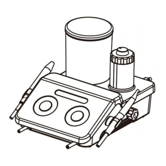
Production Installation Main Unit Front & Rear Schematic Diagram of DQ-40 2.1. Figure 2 Rear Schematic Diagram Figure 1 Front Schematic Diagram (DQ-40) (DQ-40) - Page 14 1、Ultrasonic handpiece 2、Operation panel 3、Air polishing handpiece 4、Air pressure control knob: adjust the air pressure under air polishing mode 5、Powder tank 6、Powder flow control knob 7、Water bottle 8、Air/Water separator 9、Air intake 10、Fuse 11、Socket for DC power adapter 12、Wired foot switch socket 13、Power switch 14、Check valve quick coupling...
-
Page 15: Operation Panel Of Dq-40
Operation Panel of DQ-40 2.2. Figure 3 Operation Panel of Main unit(DQ-40) - Page 16 a) POWER: power slider, under the mode of cleaning: slide it for setting power; under the mode of powder spray: slide it for setting air pressure. b) Liquid: water volume adjustment slider c) Mode selection area: G: Scaling P: Periodontal treatment E: Root canal irrigation A:Air polishing (Intelligent recognition after taking the air polishing handpiece, no need for manual...
-
Page 17: Main Unit Front & Rear Schematic Diagram Of Dq-80
Main Unit Front & Rear Schematic Diagram of DQ-80 2.3. Figure 4 Front Schematic Diagram(DQ-80) Figure 5 Rear Schematic Diagram(DQ-80) - Page 18 1、Ultrasonic handpiece 2、Display panel 3、Air polishing handpiece 4、Powder tank 5、Powder flow control knob 6、Water bottle 7、Air/Water separator 8、Air intake 9、Fuse 10、DC power supply socket 11、Wired foot switch socket 12、Power switch 13、Check valve quick coupling...
-
Page 19: Touch Panel (Dq-80)
Touch Panel (DQ-80) 2.4. Figure 6 Ultrasonic system main interface (DQ-80) - Page 20 Figure 7 Air polishing system main interface (DQ-80)
- Page 21 Air polishing Ultrasonic Scaling G: Scaling Air polishing P: Periodontal treatment Pipe cleaning E: Root canal irrigation Turn down water volume/power/air pressure Turn up water volume/power/air pressure Setting Figure 8 Settlement interface(DQ-80) Heating: Turn on/off the heating function of air polishing system Language: Chinese or English Wireless Foot Switch: Wireless foot switch matching Factory reset: Factory reset...
-
Page 22: Schematic Diagram Of Tip And Handpiece Installation
Schematic diagram of tip and handpiece installation 2.5. Figure 9 Installation diagram of tip and Endo file... - Page 23 Figure 10 Installation diagram of sand blasting nozzle...
- Page 24 Figure 11 Installation diagram of handpiece...
-
Page 25: Wireless Foot Switch Matching
Wireless foot switch matching 2.6. a) Installation diagram for the battery of DQ-40 wireless foot switch: Take off the sticker, and stick the waterproof rubber on the bottom. Button “1”, start the device Figure 12 Installation diagram for the battery of DQ-80 wireless foot switch: Take off the sticker, and stick the waterproof rubber on the bottom. - Page 26 DQ-40 wireless foot switch matching: 1)In the power-on state, press and hold the "G", "P", "E" buttons at the same time until the water volume slider indicator starts to flash slowly; 2)Keep the foot switch pressed and insert two AA batteries (operate when the water volume slider indicator starts to flash slowly) so that the foot switch enters the pairing state, the foot switch is pressed down for 3 seconds after power-on;...
-
Page 27: Air Intake And Power Supply Sockets
Air Intake and power supply sockets 2.7. Figure 14 Air Intake and power supply sockets of DQ-40/DQ-80 are the same... -
Page 28: Adjustment Of Dq-40 Water Volume And Powder Flow
Adjustment of DQ-40 water volume and powder flow 2.8. Figure 15 DQ-40... -
Page 29: Adjustment Of Dq-80 Water Volume And Powder Flow
Adjustment of DQ-80 water volume and powder flow 2.9. Figure 16 DQ-80... -
Page 30: Product Installation Steps
Product Installation Steps 2.10. Open the package, check whether all items of the device are complete according to the packing list, and place the main unit on a stable plane facing the operator. Insert the external air pipe (black) connector into the air intake connector on the back of the main unit: press the snap ring first and then insert the air inlet connector as shown in Figure 14. -
Page 31: Product Functions And Operations
Warning 1: The protective ground must be connected when the power adapter is connected to the network power. Warning 2: Do not place or install the device in which is difficult to disconnect the network power when the power adapter is connected to the network power. Product Functions and Operations Ultrasonic System 3.1. - Page 32 ⑦ Water volume: if the device is DQ-40, slide to adjust the water volume by touching water volume adjustment slider on the panel; if the device is DQ-80, adjust the water volume by pressing the "+"...
- Page 33 3.1.2. Periodontal treatment mode and operation ① Screw the tip tightly on the ultrasonic handpiece by torque wrench. Click the "P" button on the panel to enter the periodontal treatment mode. ② The other operation and adjustment methods are similar to the ultrasonic scaling mode. 3.1.3.
- Page 34 3.1.4.Torque wrench operation (See figure 9) The structure of torque wrench is designed in a special way which can control the strength of the scaling tip’s installation properly and correctly. It also can guarantee the operator screw or unscrew the tip effectively and keep the operator's hands away from being scratched during the use process. Operation Steps: 1)Put the tip into the torque wrench and hold the handpiece tightly, rotate the tip in a clockwise direction till the tip does not turnround anymore, and then it is installed.
-
Page 35: Air Polishing System
② Pick up the air polishing handpiece, then the panel will automatically jump into air polishing mode. ③ If the device is DQ-40, adjust the air pressure knob by sliding the water volume adjustment slider (see Figure 15 for details). If the device is DQ-80, adjust the water volume by clicking the "+" or "-"... - Page 36 ⑥ Adjust the water volume and air pressure to the appropriate gear. The recommended water volume and air pressure starts from 5 gears. Adjust the water volume and air pressure at any time during the clinical process according to the sensitivity of patients' teeth and dental plaque. Increasing the air pressure will enhance the cleaning effect, but will weaken the polishing effect;...
-
Page 37: Cleaning Mode
① Put distilled water or demineralised water into the water bottle; ② Pick up the ultrasonic handpiece and aim at the pool. If the device is DQ-40, click the "C" button on the interface to start cleaning the pipeline; If the device is DQ-80, click the "Clean"... -
Page 38: Setting (Not Available For Dq-40)
"A" (DQ-40) or "Cancel" (DQ-80) on the panel to stop cleaning. Setting (not available for DQ-40) 3.4. ① Click the "Setting" in the lower right corner of the screen to enter the "Function Setting" interface. See Figure 8 for details. -
Page 39: Precautions
outlet Waterless Mode Tip vibrate Air spray Enhancement mode(+1) Power increased by 3 Air pressure increased by 3 gears gears Cleaning Mode Water outlet Air outlet+water outlet Note: The power/air pressure is increased by 3 gears from the original gear in the enhancement mode, up to 12 gears, and automatically returns to the previously set gear after releasing 3 button. - Page 40 4) The use of the product must comply with the requirements of the relevant operating specifications and relevant laws and regulations of the medical department, and it is only used by trained doctors or technicians. 5)Please disinfect the ultrasonic handpiece, air polishing handpiece, tips, wrench and other accessories before using.
- Page 41 is as low as 80%. It is recommended to replace the tip if the power is low and wear to within the red line scale 11)Do not bend or grind the tip. 12)Prohibit pointing the nozzle of air polishing handpiece at people in any case. 13)It may cause eye damage if the sand powder is accidentally sprayed into the eyes.
- Page 42 18) Please rotate the powder tank cover to the specified position to seal the powder tank. 19) Please clean the connector of the water bottle before using. 20) When changing the liquid category of the water bottle after using, please adjust the water volume to the maximum and make it work in the automatic water supply mode for 30 seconds to keep the current liquid and liquid circuit clean.
-
Page 43: Handpiece
27) Please use the corresponding tip of our company. The internal thread of the tip produced by another manufacturers is rough, rusty, cracked or uses other standard threads, which are easy to be damaged and slip when used in combination with the external thread of the handpiece, so as to cause irreparable damage to the ultrasonic periodontal therapy device. - Page 44 the disinfection is completed. Notices: 1)Please use compressed air to blow off the cleaning liquid remaining in the handpiece before disinfection. 2)Ensure to remove the tip from handpiece, and do not mix with other instruments for disinfection; 3)Please pay attention to whether the handpiece is externally damaged during the use of disinfection.
-
Page 45: Tip
• Steam the handpiece in the solution • Soak the handpiece with iodine, alcohol, glutaraldehyde and other disinfectant water • Bake in the oven or microwave on high heat 4.2. The tip can be sterilized in a high-temperature and high-pressure environment. Wrench 4.3. -
Page 46: Cleaning Of Tips, Torque Wrench And Endo Wrench
Cleaning of Tips, Torque wrench and Endo wrench 4.4. Tips, Torque wrench and Endo wrench can be cleaned in ultrasonic cleaner. Troubleshooting 5.1. Troubleshooting Fault Possible cause Solutions The power cord is not plugged in Check the power plug properly Replace the fuse (Replace the T1AL The fuse in the power supply is 250 V under the guidance of the... - Page 47 The tip hasn't been screwed on to Screw the tip on the handpiece the handpiece tightly tightly by wrench The tail wire is loose from the Contact local dealer or our company board connector No ultrasonic vibration Pull out handpiece and contact us Handpiece failure or anthorized dealers Tail wire failure...
- Page 48 The amount of water volume is too Adjust the water volume to a higher Heating handpiece little grade Heating handpiece Pull out handpiece and contact Handpiece failure seriously local dealer or our company The amount of water volume is too Adjust the water volume to a higher little grade...
- Page 49 Water seeps from the connection between The waterproof O-ring is damaged Replace the waterproof O-ring the handpiece and the tail wire socket Loose Clamping nut is loose Screw the nut tightly File can not vibrate The root canal clamp holder is Replace the root canal clamp holder damaged Leakage of...
-
Page 50: 5.2 .Annotation
Pull out the handpiece and check the sandblasting tail wire for air or sand spray. If sand powder, air The handpiece or nozzle is clogged and water can be sprayed, please use a steel wire to unclog the handpiece and put it in a washing machine for cleaning. -
Page 51: Storage, Maintenance, Transportation
2) Abnormal noise of "buzzing" is sound when the tip works. 5.3 Maintenance of air polishing System 1)Touch the gear adjustment button to make the device automatically activate the air path cleaning for 5 seconds after each use of air polishing. 2)Pay attention to the gas-water separation valve behind the device before use, rotate the knob at the bottom of the gas-water separation valve to drain the liquid inside if there is liquid inside it. -
Page 52: Transportation
③ Atmospheric pressure: 70 kPa ~ 106 kPa. Transportation 6.2. • During transportation, it shall not be packed with dangerous goods. • During transportation, excessive shock and vibration shall be prevented, and carefully place, do not place it upside down. •... - Page 53 Air polishing See Chapter 2.5 for replacement handpiece methods See Chapter 2.5 for replacement Tips methods Torque wrench Endo wrench T2AH250V(DQ-40) T5AH250V(DQ-80) Fuse See Chapter 2.5 for replacement Root canal tip methods Airway pipe 4mm×6mm Power supply Electromagnetic valve...
-
Page 54: Warranty
Two-way and three-way adapters Note: This manual does not list the accessories specifications of ultrasonic scaler device in detail, please refer to the attached information and packing list. Warranty Since the date of sale, the warranty of this product is effective with its warranty card, and we are responsible for life-long maintenance. - Page 55 Sterilizable at up to 134℃ Refer to in the steam instruct Serial Keep sterilizer Manufacturer number (autoclave) manual/ attemperature booklet specified Fragile, Atmospheric Humidity Date of Temperature handle pressure limitati manufac limit with limitation ture care Inlet Pressure Foot Use-by date This way up Fuse 0.5-0.6...
-
Page 56: Environmental Protection
Endodon Maximum Periodon Scaling Minimum power power tal Mode Mode Mode For indoor use Cleaning only Mode Environmental Protection Hazardous substances Polybrom Hexavalent Polybrominated Name of Components Plumbum hydrargyru cadmium inated chromium diphenyl ethers (Pb) m(Hg) (Cd) biphenyl (Cr(Ⅵ)) (PBDE) s(PBB)... - Page 57 Hazardous substances Polybrom Hexavalent Polybrominated Name of Components Plumbum hydrargyru cadmium inated chromium diphenyl ethers (Pb) m(Hg) (Cd) biphenyl (Cr(Ⅵ)) (PBDE) s(PBB) Circuit board Sheet metal parts Switch Wire Foot switch ○: Indicates that the content of the toxic substance in all homogeneous materials of the part is below the limit requirement stipulated in SJ/T-11363-2006 Limit Requirements for Toxic and Hazardous Substances in Electronic Information Products.
-
Page 58: Manufacturer's Rights
Manufacturer's rights We reserves the right to modify the design, technology, accessories, description and packing list of the products without prior notice at any time. In case of any difference, the actual product shall prevail. Electromagnetic compatibility Warning: (1)The ME EQUIPMENT or ME SYSTEM is suitable for hospital or professional dental clinic environment (2)Don’t near active HF surgical equipment and the RF shielded room of an ME system for magnetic resonance imaging, where the intensity of EM disturbances is high. -
Page 59: Requirements For Cable Installation
(5)Portable RF communications equipment (including peripherals such as antenna cables and external antennas) should be used no closer than 30 cm (12 inches) to any part of the equipment, including cables specified by the manufacturer. Otherwise, degradation of the performance of this equipment could result. -
Page 60: Components Of Electromagnetic Compatibility
Guidance and manufacturer’s declaration - Electromagnetic Emissions 12.3. Guidance and manufacturer’s declaration - electromagnetic emissions The ultrasonic scaler DQ-40/DQ-80 is expected to be used in the electromagnetic environment specified below. The purchaser or user shall ensure that it is used in such electromagnetic environment. -
Page 61: Guidance And Manufacturer's Declaration-Electromagnetic Immunity
Guidance and manufacturer’s declaration-Electromagnetic Immunity 12.4. Guidance and manufacturer’s declaration-electromagnetic Immunity The ultrasonic scaler DQ-40/DQ-80 is expected to be used in the electromagnetic environment specified below. The purchaser or user shall ensure that it is used in such electromagnetic environment. - Page 62 The ground shall be wood, concrete or tile; if the Electrostatic ±6kV contact ±6kV contact ground covered with discharge(ESD) ±8kV air ±8kV air synthetic material, GB/T 17626.2 relative humidity shall be at least 30%. The power supply from the ±2kV for power supply ±2kVfor power Electrical fast...
- Page 63 <5%U ,last for5s 30%suspension) power failure, it is (On U ,> <5%U ,last for 5s recommended that the 95%suspension) (On U ,> ultrasonic scaler 95%suspension) DQ-40/DQ-80 be powered by an uninterruptible power supply (UPS) or the battery.
-
Page 64: Guidelines And Manufacturer's Declarations
Guidelines and manufacturer's declarations --- Electromagnetic Immunity 12.5. Guidance and manufacturer’s declarations-electromagnetic Immunity The ultrasonic scaler DQ-40/DQ-80 is expected to be used in the electromagnetic environment specified below. The purchaser or user shall ensure that it is used in such electromagnetic environment. - Page 65 Portable and mobile RF communication equipment should not be used closer to any part of the ultrasonic scaler DQ-40/DQ-80, including cables than the recommended isolation distance. This distance should be calculated by the formula corresponding to the transmitter frequency. Recommended isolation distance ...
- Page 66 RF transmitter, the survey of electromagnetic sites should be considered. If the field strength of theultrasonic scaler DQ-40/DQ-80 is higher than the RF compliance level of the above application, the ultrasonic scaler DQ-40/DQ-80 should be observed to verify its normal operation.
- Page 67 The ultrasonic scaler DQ-40/DQ-80 is expected to be used in the electromagnetic environment where radiation RF disturbances are controlled. According to the maximum output power of the communication device, the purchaser or user may prevent electromagnetic interference by maintaining the minimum distance (as recommended below) between the portable and mobile RF communication device (transmitter) and the ultrasonic scaler DQ-40/DQ-80.
- Page 68 The ultrasonic scaler DQ-40/DQ-80 has passed the test according to the requirements of IEC 60601- 1-2:2004; however, it does not guarantee in any way that it is not affected by electromagnetic...
- Page 69 Attachment: Power table of ultrasonic scaler tips Subgingival scaling Supra-gum scaling Endo irrigation Water Water Water Model Grade Model Grade Model Grade Volume volume Volume 1-12(P) 1-12(G) 1-5(E) 1-12(P) 1-12(G) 1-12(P) P12L 1-12(P) P12R 1-12(P) 1-12(P) 1-12(P)
Need help?
Do you have a question about the DQ-40 and is the answer not in the manual?
Questions and answers