Advertisement
Quick Links
Advertisement

Related Manuals for Icom IC-22S


Summary of Contents for Icom IC-22S
- Page 1 Icom IC-22S PLL Synthesized 2-Meter Transceiver Instruction Manual and Service Notes...
- Page 2 Icom IC-22S PLL Synthesized 2-Meter Transceiver Instruction Manual and Service Notes SECTION I. Specifications GENERAL Semiconductor Complement Transistors Diodes 33 to 128 depending on channels Frequency Range (for specification) 146-148 MHz Voltage 13.8 Volts DC (negative ground) Current Required 2.0 amps @ 10 Watts 0.9 Amps @ 1 Watt 0.7 amps at maximum audio...
- Page 3 Icom IC-22S PLL Synthesized 2-Meter Transceiver Instruction Manual and Service Notes SECTION II. Description This transceiver is extremely rugged and completely solid state. State of the art devices such as integrated circuits, field effect transistors, varactor and zener diodes are engineered into a tight-knit, straightforward electronic design throughout both transmitter and receiver.
- Page 4 Icom IC-22S PLL Synthesized 2-Meter Transceiver Instruction Manual and Service Notes SECTION III. Installation Unpacking Carefully remove your transceiver from the packing carton and examine it for signs of shipping damage. Should any shipping damage be apparent, notify the delivering carrier or dealer immediately, stating the full extent of the damage.
- Page 5 Icom IC-22S PLL Synthesized 2-Meter Transceiver Instruction Manual and Service Notes impedance is recommended for fixed or mobile operation. In VHF as well as HF, every watt o ERP effective radiated power will make a difference. Therefore, 10 watts output into a 3 db gain antenna yields 20 watts effective radiated power, assuming a low VSWR, of course.
- Page 6 Icom IC-22S PLL Synthesized 2-Meter Transceiver Instruction Manual and Service Notes The matrix board may be removed by taking out the hold-down screw at the end of the board and pulling gently straight up on the other end to disconnect the matrix from the connector.
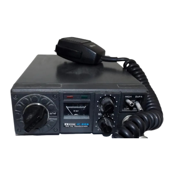
- Page 7 Icom IC-22S PLL Synthesized 2-Meter Transceiver Instruction Manual and Service Notes SECTION IV. Control Functions High-Off-Low Switch Opens or closes the 12 VDC source voltage to the transceiver. “In High” position, output power is 10 watts. “In Low” position, output power is 1 watt.
- Page 8 Icom IC-22S PLL Synthesized 2-Meter Transceiver Instruction Manual and Service Notes SECTION V. Operation Initial Preparations Connect the microphone to the microphone jack. Connect the antenna to the antenna coax connector. Make sure the coax line is of the correct impedance (50 ohms) and is neither shorted nor open.
- Page 9 Icom IC-22S PLL Synthesized 2-Meter Transceiver Instruction Manual and Service Notes SECTION VI Theory of Operation TRANSMITTER Microphone, pre-amplifier circuit The pre-amplifier circuit is composed of Q30, Q29, in an NPN, PNP direct-coupled 2-stage amplifier configuration. The low noise transistors used and application of a large amount of feedback in the 1st stage gives a high signal-to-noise ratio and high stability.
- Page 10 Icom IC-22S PLL Synthesized 2-Meter Transceiver Instruction Manual and Service Notes Interstage Amplifier BPF output is amplified up to about 2 mW in the Q22 stage that is a MOSEFT with good linearity. Low Level Amplifier Interstage amplifier output is amplified to about 100 mW by stage Q19, which also functions as an ALC circuit.
-
Page 11: Phase Locked Loop
Icom IC-22S PLL Synthesized 2-Meter Transceiver Instruction Manual and Service Notes RECEIVER R.F. Amplifier Antenna input or self contained antenna signals pass through switching diode D-40 located in the PA section to the RF amplifier Q2 where it is amplified and passed to the R.F. filter section. Out-of- band signals are attenuated by the band pass filters. - Page 12 Icom IC-22S PLL Synthesized 2-Meter Transceiver Instruction Manual and Service Notes Local oscillator The overtone oscillator in Q7 is provided to reduce spurious signals resulting from multiplication of the fundamental oscillator. L6 is provided in series with the crystal to facilitate frequency adjustment.
- Page 13 Icom IC-22S PLL Synthesized 2-Meter Transceiver Instruction Manual and Service Notes Reference oscillator divider IC3 is an IC used to produce the reference frequency for the synthesizer, and includes a quartz crystal oscillator and a 12-stage high speed divider. The oscillator produces 7.68 MHz oscillations which the high-speed divider section divides by 1024 to give the 7.5 kHz reference pulses.
- Page 14 Icom IC-22S PLL Synthesized 2-Meter Transceiver Instruction Manual and Service Notes Power supply Reverse connection protection circuit If power with the wrong polarity is applied, D28 is forward biased and there is, therefore, a large current flow which blows the fuse provided on the external lead, preventing damage to circuit elements.
- Page 15 Icom IC-22S PLL Synthesized 2-Meter Transceiver Instruction Manual and Service Notes SECTION VII Charts Diode Matrix Chart Freq. "N" +Offset -Offset 144.390 144.990 143.790 144.405 145.005 143.805 144.420 145.020 143.820 144.435 145.035 143.835 144.450 145.050 143.850 144.465 145.065 143.865 144.480 145.080...
- Page 16 Icom IC-22S PLL Synthesized 2-Meter Transceiver Instruction Manual and Service Notes Freq. "N" +Offset -Offset 145.020 145.620 144.420 145.035 145.635 144.435 145.050 145.650 144.450 145.065 145.665 144.465 145.080 145.680 144.480 145.095 145.695 144.495 145.110 145.710 144.510 145.125 145.725 144.525 145.140 145.740...
- Page 17 Icom IC-22S PLL Synthesized 2-Meter Transceiver Instruction Manual and Service Notes Freq. "N" +Offset -Offset 145.710 146.310 145.110 145.725 146.325 145.125 145.740 146.340 145.140 145.755 146.355 145.155 145.770 146.370 145.170 145.785 146.385 145.185 145.800 146.400 145.200 145.815 146.415 145.215 145.815 146.415...
- Page 18 Icom IC-22S PLL Synthesized 2-Meter Transceiver Instruction Manual and Service Notes Freq. "N" +Offset -Offset 146.400 147.000 145.800 146.415 147.015 145.815 146.430 147.030 145.830 146.445 147.045 145.845 146.460 147.060 145.860 146.475 147.075 145.875 146.490 147.090 145.890 146.505 147.105 145.905 146.520 147.120...
- Page 19 Icom IC-22S PLL Synthesized 2-Meter Transceiver Instruction Manual and Service Notes Freq. "N" +Offset -Offset 147.090 147.690 146.490 147.105 147.705 146.505 147.120 147.720 146.520 147.135 147.735 146.535 147.150 147.750 146.550 147.165 147.765 146.565 147.180 147.780 146.580 147.195 147.795 146.595 147.210 147.810...
- Page 20 Icom IC-22S PLL Synthesized 2-Meter Transceiver Instruction Manual and Service Notes Freq. "N" +Offset -Offset 147.765 148.365 147.165 147.780 148.380 147.180 147.795 148.395 147.195 147.810 148.410 147.210 147.825 148.425 147.225 147.840 148.440 147.240 147.855 148.455 147.255 147.870 148.470 147.270 147.885 148.485...
- Page 21 Icom IC-22S PLL Synthesized 2-Meter Transceiver Instruction Manual and Service Notes Voltage Chart Transmit Receive Part Base Gate 2 Collector Emitter Base Gate 2 Collector Emitter Comments Gate 1 Drain Source Gate 1 Or Drain Source 0.20V -25.0V 0.26V 8.2V 6.8V...
Need help?
Do you have a question about the IC-22S and is the answer not in the manual?
Questions and answers