
Related Manuals for Xinje VB5N Series

Summary of Contents for Xinje VB5N Series
- Page 1 VB5N series frequency inverter User manual WUXI XINJE ELECTRIC CO., LTD. No. INV C 10 20140403 204...
- Page 2 Table of Contents Preface ——————————————— Safty Precautions VB5N ——————————————— Series Inverter Product Introductions User Manual ——————————————— Installation and Wiring ——————————————— Operation Descriptions ——————————————— Function Parameters ——————————————— Fault Diagnosis and Disposal ——————————————— Maintenance ——————————————— Communication Protocol ———————————————...
- Page 3 The device and its components can only be used in the applications described in the catalog and the technical manuals, can only be connected with devices or components from other manufacturers which have been approved or recommended by Xinje. The products will run normally in the condition of been transported, stored, configured and installed correctly, been operated and maintained as recommended.
-
Page 5: Table Of Contents
VB5N series inverter CATALOG PREFACE ............................1 SAFETY PRECAUTIONS .......................2 1 PRODUCT INTRODUCTION .......................6 1-1. Product overview ..................................6 1-2. Product technical specification ............................... 7 1-3. Product appearance ................................. 9 1-4. Product dimension ................................. 10 2 INSTALLATION AND WIRING ....................11 2-1. - Page 6 3-2-1. Keyboard layout ................................23 3-2-2. Keyboard function ................................23 3-2-3. Fucntion description of LED and indicator ........................24 3-2-4. Display of the operation panel ............................24 3-2-5. Panel operation method ..............................25 3-3. Power on the inverter ................................28 3-3-1.
- Page 7 VB5N series inverter 7-2. Communication protocol ............................... 89 7-2-1. Communication networking mode ........................... 89 7-2-2. Communication protocol modes ............................90 7-2-3. Communication port ................................. 90 7-3.Modbus-RTU communication protocol ..........................90 7-3-1. Character structure ................................90 7-3-2. Communication information............................. 91 7-3-3.Communication parameter ..............................93 APPENDIX A ACCESSORIES .....................
-
Page 9: Preface
Preface ——Essential introduction for this manual Thank you for purchasing Xinje inverter, this manual should be read and understood before attempting relevant operations. 1. Purpose of this manual This manual offers guidance and introductions about how to use and maintains the inverter correctly, including functions, usages, installation, maintenance, etc. -
Page 10: Safety Precautions
VB5N series inverter Safety Precautions Upon unpacking, please confirm that: Check whether the model and the rated values on the nameplate of the inverter are in accordance with your order. Check if there is any damage occurred during transportation; pleases contact us or the distrib- utor if you find any missing or damage of the products. - Page 11 VB5N series inverter 1. Confirm that the voltage of the main AC power supply satisfies the rated voltage of the Inverter. Injury and fire may occur if the voltage is not right. 2. Do not perform voltage withstand tests on the Inverter. Otherwise, semiconductor elements and other devices can be damaged.
- Page 12 VB5N series inverter Mechanical resonance point of load The inverter may encounter the mechanical resonance point of load within certain output frequency range. Jump frequen- cies have to be set to avoid it. Capacitor and resistor Because the inverter output pulse wave, capacitor and resistors shouldn't be connected with the output terminals of the in- verter, or the inverter may trip or components may be damaged;...
- Page 13 VB5N series inverter lout 100% 1000 2000 3000 4000 (m) Fig. 0-2 The relationship between the altitude and rated current of frequency inverter About protection classes The protection class of V5/F5 series inverter IP20 is reached in the case of status display unit or keyboard.
-
Page 14: Product Introduction
1-1. Product overview VB5N series inverter is produced by Xinje with high performance, easy operating and low noise. It is a innovative product with a series advanced and practical running and control functions such as practical PI, flexible input and output terminals, parameter modification online, fixed length control, traverse operation, RS485 control, bus-mastering. -
Page 15: Product Technical Specification
VB5N series inverter 1-2. Product technical specification 1. Technical specification 220V VB5N-2_ _ _ Type 0.75 Output Match Motor (kW) Rated Output Current (A) Rated Voltage (V) AC 200 0~500 Frequency Range (Hz) 0.01 Frequency Resolution (Hz) Overload Ability 150%Rated Current for 1 minutes, 180% Rated Current for 1 second... - Page 16 VB5N series inverter 2. General Specification Optimized space voltage vector SVPWM modulation Modulation mode Control mode SVPWM control (dead zone compensation for optimized low-frequency) Digital Setting: max frequency × ± 0. 01%; Frequency precision Analog Setting: max frequency × ± 0.2% Frequency resolution Digital Setting: 0.01Hz;...
-
Page 17: Product Appearance
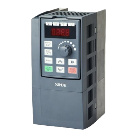
VB5N series inverter 1-3. Product appearance VB5N single phase 0.75kW: LED light 4-digits LED display Analog potentiometer Panel buttons Mounting hole VB5N three phase 2.2KW~3.7KW VB5N single phase 0.75KW... -
Page 18: Product Dimension
VB5N series inverter 1-4. Product dimension VB5N single phase 0.75KW (Unit: mm) VB5N three phase 2.2~3.7KW (Unit: mm) -
Page 19: Installation And Wiring
VB5N series inverter Installation and Wiring 2-1. Installation environment 2-1-1. Environment requirement Ambient tempeature: -10º C~40º C. The inverter should be derated when the temperature over 40º C, at the same time ventilation and heat dissipation should be enhanced. -
Page 20: Wiring Of Main Circuit Terminals
VB5N series inverter shown in Fig2-3. In order to make the input over-current protection and power off maintenance easily, the inverters should connect power supply via braker. The connection cable of relay I/O circuit (X1~X4, X6, FWD, REV, OC, DO) should select the twisted-pair or shield cable with diameter over 0.75 mm². -
Page 21: Basic Running Wiring
VB5N series inverter I/O terminals of main circuit: Table 2-1 main circuit I/O terminals Voltage Terminal Function L, N Single phase AC 220V input VB5N P+, PB Brake resistor terminal Single phase 220V U, V, W Three phases AC output... -
Page 22: Setting And Wiring Of Control Circuit
2-5-1.Position and function of terminals and jumpers on control panel Please open the front cover of inverter, there is the PCB board inside. The jumper is on the board. 0.7KW VB5N series single phase inverter jumper location Fig 2-4 (a) control panel terminal jumper location 2.2~3.7KW VB5N three phase inverter jumper location... -
Page 23: 2-5-2.Terminals On Control Panel
VB5N series inverter 2.2~3.7KW VB5N(S) three phase inverter jumper location Fig 2-4 (c) control panel terminal jumper location The position of jumpers are shown in Fig. 2-4, the function of jumper terminals are shown in Table 2-3 and the function de- scriptions of jumpers and their setting method are shown in Table2-2. - Page 24 VB5N series inverter 2. Control circuit terminal J3 (VB5N-S has the same terminals of VB5N, but some terminals don’t have real functions): X1 X2 X3 FWD REV COM 10V CI VB5N single phase 0.75KW 485+ X1 X3 FWD REV VB5N three phase 2.2~3.7KW...
-
Page 25: Analog I/O Terminal Wiring
VB5N series inverter Supply +10V power supply +10V power supply Max output current: 50mA (negative terminal: GND) +10V Reference ground of analog signal and power supply common +10V power supply COM is isolated with GND inside terminal inverter +24V power supply... - Page 26 VB5N series inverter Connection of inverter RS485 port and superior device: Superior device Shield RS232 (DB9) RS485/RS232 converter cable Signal Terminal Name Cover 5V power + Send data Receive data 5V power - Frequency inverter Inverter Terminal Name Terminal...
-
Page 27: Mounting Guide According With Emc
VB5N series inverter If the communication is still failed with the above connection methods, you can adopt the following methods: (1) Use separate power supply for PLC or isolate its power supply. (2) Use magnetism ring for the cable and reduce the inverter’s carrier frequency. -
Page 28: Local Wiring And Grounding
VB5N series inverter (1)The equipment and the signal cables should be far away from the inverter. The signal cables should be shield- ed and the shielding layer should be grounded. The signal cables should be located far away from the input/output cables of the inverter. -
Page 29: Operating Instructions
VB5N series inverter Operating Instructions 3-1. Run the inverter 3-1-1. Command channel of inverter We can control the inverter’s START, STOP, JOG and other running actions by three command channels. 1. Operation panel Control by keys on the operation panel (default setting) 2. -
Page 30: Running Modes
VB5N series inverter 3-1-4. Running modes VB5N inverter has 5 kinds of running modes which can be sequenced according to the priority: Jog running→Close loop running→PLC running→Multi-speed running→Simple running, as shown in Fig. 3-1. 0: Jog running When the inverter is in the stopp state, it will running according to jog frequency (refer to P3.06~P3.08 for details) af- ter receiving jog running command (e.g after pressing... -
Page 31: Use The Keyboard
VB5N series inverter 3-2. Use the keyboard 3-2-1. Keyboard layout Start, speed, stop, brake, running parameter setting and control of the peripheral can be performed by inverter’s operation panel and control terminals; operation panel is shown in Fig.3-2. Fig. 3-2 Illustration of operation panel 3-2-2. -
Page 32: Fucntion Description Of Led And Indicator
VB5N series inverter 3-2-3. Fucntion description of LED and indicator The operation panel consists of 4-bit 8-segment LED, 3 unit indicators and 3 state indicators. 3 state indicators locate above the LED in the operate panel. From left to right: forward indicator FWD, reverse indicator REV, alarm indicator ALM. -
Page 33: Panel Operation Method
VB5N series inverter 3. Alarm information When then inverter detects error signal, the panel will display error code, the code will flicker to catch your attention as shown in Fig.3-5; Press key to view the relative error parameters in stopping status, and then press to switch to error code display. - Page 34 VB5N series inverter 50.00 b-01 parameter b-02 parameter b-03 parameter display Output Output Output frequency frequency current voltage Button operation parameter b-14 parameters b-04 Generatrix Set length voltage Fig. 3-7 Setting the parameters in running status (1) The default setting is to display parameter b-00~b-08, you can view other status parameters by changing P3.41 and P3.42.
- Page 35 VB5N series inverter 3. Jog Suppose the current running command channel is operate panel, machine is standby, jog frequency is 5Hz: 50.00 0.01 5.00 0.01 50.00 display Release Press Stop status Keep Button … Stop Show Show operation Output fre-...
-
Page 36: Power On The Inverter
VB5N series inverter Note: (1) Press key to check parameter P6 in error code display mode, the range is P6.01~P6.06, press key, parameter No. will firstly displayed and the parameter value will be displayed after 1s. (2)While checking, press key to back to error code display. - Page 37 VB5N series inverter Start Wiring as chapter 2.4 Wiring is OK ? Input voltage is OK ? Show dynamic screen ? Contactor ON sound? Show set frequency? Power on is ok Power on failed Check reason Fig. 3-12 Procedures of starting the inverter for the first time...
-
Page 38: Function Parameters
VB5N series inverter Function Parameters 4-1. Function code ○: Parameters can be changed while running ×: Parameters can not be changed while running *: Parameters can only be read, can not be changed 1. Basic running parameters (Group P0) Group P0: Basic running parameters... - Page 39 VB5N series inverter S curve P0.14+P0.15<90% 10.0%~80.0%(Acc/Dec time) 0.1% 60.0% ○ P0.15 Linear time of S curve P0.14+P0.15<90% 0: second × P0.16 Acc/Dec time unit 1: minute Accerlate time 1 0.1~6000.0 10.0 ○ P0.17 Decerlate time 1 0.1~6000.0 10.0 ○...
- Page 40 VB5N series inverter min setting of CI ○ P1.09 Max setting of CI P1.07 ~10.00V 0.01V 10.00V 0.00~highest frequency ○ P1.10 Frequency 0.01Hz 50.00Hz max setting of CI 0.1~20.0K ○ P1.11 input pulse 0.1K 10.0K frequency PULSE 0.0~P1.14 ○ P1.12 setting 0.1K...
- Page 41 VB5N series inverter 4. Auxiliary running parameters (Group P3) Group P3: Auxiliary running parameters Minmum Factory Change Parameter Name Range unit setting 0: VI+CI × P3.00 Combination of 1: VI-CI frequency input 2: External pulse+VI+ Increase/Decrease key 3: External pulse-VI-...
- Page 42 VB5N series inverter 0: disabled × P3.03 Auto energy-saving func- 1: Enabled tion 0: disabled × P3.04 AVR function 1: enable all the time 2: Disabled when decelerating 0~150% × P3.05 Slip frequency compen- sation 0.10~50.00Hz 0.01Hz ○ P3.06 Jog frequency 5.00Hz...
- Page 43 VB5N series inverter ○ P3.26 Multi-frequency 1 Min frequency~max frequency 0.01Hz 5.00Hz ○ P3.27 Multi-frequency 2 Min frequency~max frequency 0.01Hz 10.00Hz ○ P3.28 Multi-frequency 3 Min frequency~max frequency 0.01Hz 20.00Hz ○ P3.29 Multi-frequency 4 Min frequency~max frequency 0.01Hz 30.00Hz ○...
- Page 44 VB5N series inverter 3: Multi-speed control terminal 3 4: Exteral forward jog in- 5: Exteral reverse jog input 6: Acc/Dec time terminal 1 7: Acc/Dec time terminal 2 8: Acc/Dec time terminal 3 9: 3-wire operation control 10: Free stop (FRS)
- Page 45 VB5N series inverter 34: External interrupt input 35: Pulse frequency input (only valid for X6) 36: Actual length reset input × P4.01 Function selection of Ditto input terminal X2 × P4.02 Function selection of Ditto input terminal X3 × P4.03...
- Page 46 VB5N series inverter arrived 14: Inverter running prepa- ration is finished (RDY) 15: Inverter fault 16: Running with start frenquence 17: DC brake when startup 18: brake when stop 19: High and low limit of swing frequency 20: set running time arrived ×...
- Page 47 VB5N series inverter (FAR) 102: frequency level detect signal (FDT1) 103: frequency level detect signal (FDT2) 104: overload pre-alarm (OL) 105: inverter under voltage blockade and stop (LU) 106: external error stop (EXT) 107: output frequency reach upper limit (FH)
- Page 48 VB5N series inverter 6. Protective function parameters (Group P5) Group P5: Protective function parameters Minmum Change Parameter Name Range Default setting unit 0: Inverter lock the output × P5.00 Motor overload protection 1: Disabled mode selection 20~120% 100% × P5.01...
- Page 49 VB5N series inverter P6.08 First 3 times fault records First 3 times fault records P6.09 First 4 times fault records First 4 times fault records P6.10 First 5 times fault records First 5 times fault records P6.11 First 6 times fault records First 6 times fault records 8.
- Page 50 VB5N series inverter Group P8: Simple PLC operation parameters Minmum Default Parameters Name Range Change unit setting 0000~1113 0000 × P8.00 Simple PLC operation mode selection Lowest bit: mode selection 0: Disabled 1: Stop after single cycle 2: keep the final value after single cycle...
- Page 51 VB5N series inverter 10. Swing frequency and measurement functions parameters (Group 9) Group P9: Swing frequency and measurement function parameters Minmum unit Default Parameters Name Range Change setting 0: Disabled × P9.00 Swing frequency selection 1: Enabled 00~11 × P9.01...
- Page 52 VB5N series inverter 2~48 × PA.05 Poles of motor Dependent on in- verter’s model 0.1~5000.0mH × PA.06 Stator inductance of motor 0.1mH Dependent on in- verter’s model 0.1~5000.0mH × PA.07 Rotor inductance of motor 0.1mH Dependent on in- verter’s model 0.1~5000.0mH...
- Page 53 VB5N series inverter 13. Default setting (Group PF) Group PP: Default Setting Minmum Default Parameter Name Range Change unit setting PF.00 Default password 0: No password 0000 ○ PF.01 User’s password 0001-9999: passwor protection PF.02 Software version PF.03~PF.10 Reversed 14. B Monitor function parameters...
-
Page 54: Function Code Description
VB5N series inverter 4-2. Function code description 4-2-1. Basic operating function parameters (Group P0) Range: 0~1 P0.00 Control mode selection 0: V/F control 1: Open loop vector control Range: 1~8 P0.01 Frequency setting channel selection 0: Panel analog potentiometer setting... - Page 55 VB5N series inverter Range: 0, 1, 2 P0.03 Running command channel selection 0: Panel control to stop, start the inverter. 1: Terminal control Use external terminal FWD, REV, X1~X6 to start or stop the inverter. 2: Serial port control To start or stop the inverter via RS485 port.
- Page 56 VB5N series inverter Output voltage Vmax Output frequency Fmax FB FH Fig. 4-2 Characteristic parameter FH(highest frequency), FL(lowest frequency) are defined by P0.19 and P0.20 . Range: 0.0%~30.0% 2.0% P0.09 Torque boost Improve inverter low frequency torque characteristics, boost-compensate the output voltage.
- Page 57 VB5N series inverter P0.12 Carrier frequency Range: 1.0K~14.0K 8.0K The default carrier frequency below 3.7kW inverter is 5.0 kHz; it is 3.0 kHz for 5.5kW and larger inverters. 18.5kW and larger inverter is 5.0kHz. Carrier frequency will affect the motor’s noise and heat loss.The relationship among carier frequency, motor noise, leak...
- Page 58 VB5N series inverter Range: 10.0%~80.0% (Acc/Dec time), P0.14+P0.15<90% 60.0% P0.15 Linear time of S curve P0.14 and P0.15 are only valid when Acc/Dcc mode is S curve Acc/Eec mode (P0.13 =1) and P0.14+P0.15 < 90%. Low speed time of S curve is shown in Fig.4-5 ③, the output frequency slope increases from 0.
- Page 59 VB5N series inverter 0.0% P0.26 V/F voltage value V2 Range: P0.24~P0.28 P0.27 V/F frequency value F3 Range: P0.25~P0.07 basic running frequency 0.00Hz Range: P0.26~ 100.0% 0.0% P0.28 V/F voltage value V3 This group of parameters defines the flexible V/F setting modes of this inverter to satisfy the requirement of different loads.
-
Page 60: Parameters Of Frequency Setting (Group P1)
VB5N series inverter 4-2-2. Parameters of frequency setting (Group P1) Range: 0.01~30.00s P1.00 Time constant of analog filter 0.20s The inverters filter time for sample value when set the frequency by analog channel. If the wiring is too long or noise is too serious, increase this parameter to improve the frequency stability. -
Page 61: Starting And Braking Parameters (Group P2)
VB5N series inverter The relationship between CI and setting frequency: Set frequency Set frequency Fmax Fmax Fmin Fmin Amin Amin Amax Amax (2) negative function (1) positive function A:CI set frequency Amin:min setting Fmin:frequency of min setting Amax:max setting Fmax:max frequency of max setting... - Page 62 VB5N series inverter Power Motor speed Output frequency of inverter Fig.4-9 Speed track then start Note: (1) Starting mode 0: It is recommended for general application or when the inverter drives synchromous motor. (2) Starting mode 1: It is suitable for small inertial load that motor will forward or reverse rotate without load and it is not recommended for big inertial load.
- Page 63 VB5N series inverter Output frequency time Output voltage (effective value) DC brake value time DC brake time Run command Fig.4-11 Starting mode 1 Output frequency Start frequency of brake time Output voltage (Effective value) DC brake value Brake time Run command Fig.
-
Page 64: Auxiliary Running Parameters (Group P3)
VB5N series inverter 4-2-4. Auxiliary running parameters (Group P3) Combination of frequency setting Range: 0~20 P3.00 channel When P0.01(Frequency setting chanel)= 8, set the frequency setting channel combination via P3.00. 0: VI+CI 1: VI-CI 2: External pulse +VI+Increase/Decrease key 3: External pulse-VI-Increase/Decrease key 4: External pulse+CI... - Page 65 VB5N series inverter 0: Disabled 1: Enabled Inverter can saves the energy through detecting the load current; adjust output voltage when motor has no load or light load running. This function is used to the situation of stable load and speed.
- Page 66 VB5N series inverter Speed down time of jog Jog frequency Jog frequency Speed up time of jog Jog signal Jog signal Fig 4-14 Jog operation Note: (1) Jog operation can be controlled by panel, terminal and serial port. (2) If jog operation command has been canceled, the inverter will decelerate and stop.
- Page 67 VB5N series inverter The real running frequency= the proportion * frequency command receiving from RS485 port. This parameter can also set running frequency proportion of several inverters in multimachine linkage mode. Accelerate time 2 Range: 0.1~6000.0 10.0 P3.14 Decelerate time 2 Range: 0.1~6000.0...
- Page 68 VB5N series inverter Range: 0~65.535K hour 0.000K P3.39 Set running time Range: 0~65.535K hour P3.40 Accumulate running time If accumulated running time reach the setting time (P3.39), the inverter will output signal, refer to function P4.08~P4.09. P3.40 refers to the accumulating running time from out of factory till now.
-
Page 69: Function Parameters Of Terminal (Group P4)
VB5N series inverter 4-2-5. Function parameters of terminal (Group P4) Range: 0~37 P4.00 Function selection of input terminal X1 Range: 0~37 P4.01 Function selection of input terminal X2 Range: 0~37 P4.02 Function selection of input terminal X3 Range: 0~37 P4.03... - Page 70 VB5N series inverter Frequency setting Acc/Dec time Acc/Dec time 1 Common running frequency Acc/Dec time 1 frequency 1 Acc/Dec time 2 frequency 2 Acc/Dec time 3 frequency 3 Acc/Dec time 4 frequency 4 Acc/Dec time 5 frequency 5 Acc/Dec time 6...
- Page 71 VB5N series inverter Breaker R (R) Power supply T (T) Fig.4-19 Wire of multi-speed Fig.4-20 External device fault input 4~5: External jog input JOGP/JOGR. When choose terminal control (P0.03=1), JOGP is forward jog operation, JOGR is reverse jog operation. Jog operating frequency and jog Acc/Dec time are defined in P3.06~P3.08.
- Page 72 VB5N series inverter to Fig.4-20. 19~21: Frequency setting channel 1. Different ON/OFF combination of terminals 19, 20 and 21 can select frequency as shown in Table 4-4. The priority of terminal setting and function code P0.01 setting: the final setting is valid.
- Page 73 VB5N series inverter once the interrupt input signal release, the inverter will auto-track speed and continue to run. 35: Pulse frequency input (only valid for X6). Set frequency via this terminal. The relationship between input pulse and setting frequency please refer to P1.11~P1.15.
- Page 74 VB5N series inverter 3: 3-wire control mode 2 SB1: Stop button SB2: Running button Run direction Forward Reverse Fig.4-24 3-wire control mode 2 Xi is the multi-function input terminal of X1~X6, here you should define its function to No.9 “3-wire control mode”.
- Page 75 VB5N series inverter 4: Overload pre-alarm (OL) . If the output current is higher than the value in P4.24 and the time is longer than the value in P4.25, the inverter will output indicate signals. This function is mainly used in pre-alarm.
- Page 76 VB5N series inverter Output Set frequency Checking range Time Time Fig 4-26 Frequency arriving signal Range: 0.00~upper limit of frequency P4.13 FDT1 (frequency level) voltage 10.00Hz Range: 0.00~50.00Hz P4.14 FDT1 lag 1.00Hz Range: 0.00~upper limit of frequency P4.15 FDT2 (frequency level) voltage 10.00Hz...
- Page 77 VB5N series inverter PID feedback 0~10V 0~10V 0~10V/4~20mA For analog output AO, you can adjust the output gain to change the measuring range or calibrate the meter. Range: 0, 1 P4.19 AO output mode 0: 4 ~20mA 1: 0 ~10V Range: 0~120 P4.20...
-
Page 78: Protection Function Parameters (Group P5)
VB5N series inverter Output current P4.24 detection level P4.25 time P4.25 time time Overload alarm effective Time Fig.4-29 Overload alarm 4-2-6. Protection function parameters (Group P5) Range: 0,1 P5.00 Motor overload protection mode selection This parameter defines the protection mode when overload or overheat occurs. - Page 79 VB5N series inverter Note: When one inverter run with multi-motors, inverter’s thermal relay protection will be disabled. Therefore, please install thermal relay in the input wire of each motor to protect motor more efficiently. Range: 0, 1 P5.02 Over-voltage speed loss selection...
-
Page 80: Fault Recording Parameters (Group P6)
VB5N series inverter P5.06=1, Auto current limiting function is enabled when constant speed running; In auto current limiting process, the inverter output frequency may change; therefore, if the inverter output frequency is required to be stable, this function is not recommended. - Page 81 VB5N series inverter Breaker Power suply Pressure sensor Forward /stop 4~20mA 1~3K Fig.4-32 Analog feedback control system with internal PI Principle diagram of inverter’s internal PI adjustor is shown below: Proportion Close-loop gain (P7.10) Close-loop Preset value Difference Close-loop adjust feature...
- Page 82 VB5N series inverter Range: 0, 1 P7.00 Close-loop function selection 0: Close-loop control is disabled 1: PI close-loop control is enabled Range: 0, 1, 2 P7.01 Close-loop setting channel 0: Digital setting 1: VI (0~10V) voltage setting 2: CI analog setting. 0~10V voltage or 4~20mA current are available. For speed close-loop, 10V corresponds to the syn- chronized speed of the motor’s max output frequency...
- Page 83 VB5N series inverter The larger the proportion gain KP, the quicker the response. Too large value may lead to surge easily. Deviation can not be eliminated through adjusting proportiaon gian KP, integral gain KI can be used to form PI control to eliminate the deviation.
-
Page 84: Simple Plc Operation Parameters (Group P8)
VB5N series inverter For example: Fig 4-39: Actual set frequency Original set frequency Fa: zero-frequency run threshold Fb: Pa+ zero-frequency backlash Fig.4-39 zero-frequency backlash Start process: After start command is sent, the motor will start and accelerate to the preset frequency in the Acc time when the setting frequency reaches or exceeds Fb. - Page 85 VB5N series inverter Simple PLC run 500ms Indication of PLC stage finished Indication of PLC cycle finished Fig.4-40 Simple PLC running In Fig 4-40, a are the Acc/Dec time of each stage and they are set by Acc/Dec time parameters P0.17, P0.18 and P3.14~P3.2.
- Page 86 VB5N series inverter RUN command Fig. 4-42 PLC holding mode after single cycle PLC run First cycle Second cycle RUN command STOP command Fig. 4-43 PLC continuous running mode 3: Continuous cycle. See Fig.4-43, inverter start next cycle after one cycle finished, it will stop when stop command is input.
- Page 87 VB5N series inverter Interrupt signal Output frequency Hz time stage2 stage1 stage2 Run time Rest time a1:stage1 speed up time a2:stage2 speed up time a3:stage3 speed up time d2:stage2 speed down time F1:stage1 frequency F2:stage2 frequency F3:stage3 frequency Fig.4-44 PLC start mode 1 Hundred bit: PLC status parameter storage selection when power-off 0: Not save.
-
Page 88: Swing Frequency Function Parameters (Group P9)
VB5N series inverter 0: Run forward 1: Run reverse 2: Decided by operating instructions Hundred bit of LED: Acc/Dec time selection 0: Acc/Dec time 1 1: Acc/Dec time 2 2: Acc/Dec time 3 3: Acc/Dec time 4 4: Acc/Dec time 5... - Page 89 VB5N series inverter Range: 00~11 P9.01 Swing frequency running mode Lowest bit of LED:input mode 0: Auto input mode. The inverter will run at preset frequency (P9.02) for a while (P9.03), and then enter the swing fre- quency status. 1: Terminal manual input mode. If the multi-function terminal (Xi is set to No.25 function) is enabled, the inverter will enter swing frequency status.
-
Page 90: Vector Control Parameters (Group Pa)
VB5N series inverter Note: (1) The actual length (terminal Xi is defined to function 36) can be cleared by multi-function input terminal. The actual length can be calculated only after this terminal is disconnected. (2) Actual length (P9.09) will be saved after power off. -
Page 91: Special Application Function Parameters (Group Pb)
VB5N series inverter torque for large load. Range: 100~150 PA.17 Excitation In vector control mode, this parameter is used to adjust the stator flux intensity. It can improve the vector torque output perfor- mance by setting this parameter. Please don’t set it too large avoid flux supersaturated. -
Page 92: Fault Diagnosis And Solution
- PF.02 Software version Software version is set by Xinje company, cannot be changed. Fault Diagnosis and solution 5-1. Fault diagnosis and solution When fault occurs, the error code will show in LED display, the inverter stops outputting and the fault relay contactor is acti- vated. - Page 93 VB5N series inverter decelerating Potential energy load or big inertia load Increase the brake power of external brake unit Abnormal input voltage Check input power supply Over-voltage Too short Acc/Dec time Increase the Acc/Dec time E-06 when constant speed Abnormal change of input voltage...
-
Page 94: Check The Fault Records
VB5N series inverter detection circuit Auxiliary power supply is damaged Ask factory or agent for service is error Hall part is damaged Ask factory or agent for service Amplifying circuit is abnormal Ask factory or agent for service Baud rate is not suitable... -
Page 95: Maintenance
VB5N series inverter Maintenance 6-1. Maintenance Environment effections such as ambient temperature, humidity, fog, internal component aging and other factors will give rise to the occurrence of potential faults. Therefore, it is necessary to daily check and routine maintain the inverters. -
Page 96: Warranty Of The Inverter
(3) Running time : less than 12 hours per day. 6-3. Warranty of the inverter Xinje Company will offer warranty service in the case of the following situations: (1) The warranty range only points to the inverter; (2) We will take the responsibility of 15 months defects liability period for any faults or damages under the normal opera- tion conditions. -
Page 97: Communication Protocol
VB5N series inverter Communication Protocol 7-1. Overview of communication protocol The inverters have RS485 communication port and adopt MODBUS communication protocol. There- fore, the inverter can be set as a slave to communicate with the marter (such as PLC and PC) which has the same communicatin port and protocol;... -
Page 98: Communication Protocol Modes
VB5N series inverter 7-2-2. Communication protocol modes The inverter can be master and slave in RS485 network. If it is master, it can control other inverters made by our company to realize multi-machine linkage.If it is slave, PC or PLC (master) can control it. -
Page 99: Communication Information
VB5N series inverter 7-3-2. Communication information 1. RTU mode: START Keep no signal input > =10ms Address Communication address: 8-bit binary address Function Function code: 8-bit binary address DATA (n - 1) Data: …………… N*8-bit data, N< =8, Max=8 bit... - Page 100 VB5N series inverter Request mode Response mode Address Address Function code Function code Register address Register address Data Data CRC CHECK Low CRC CHECK Low CRC CHECK High CRC CHECK High (3) Command mode: 08H circuit test This command is used to test if the communication between the device (master) and inverter (slave) is normal.
-
Page 101: 7-3-3.Communication Parameter
VB5N series inverter 5. Parity code RTU mode: Double bytes hex number CRC field has two bytes 16-bit binary number. It is added to the message after calculating by sending terminal. The low byte is added at first, and then is the high byte. CRC high byte is the last byte to be sent. - Page 102 VB5N series inverter 210BH Read inverter software version I/O terminal status Bit0: X1 Bit1: X2 Bit2: X3 Bit3: X4 210CH Bit4: X5 Bit5: X6 Bit6: FWD Bit7: REV Bit8: OC Bit9: relay output GGnnH Read data of function (GG: Group No.
-
Page 103: Appendix A Accessories
VB5N series inverter Appendix A Accessories A-1. Brake resistor VB5N and VB5N-S inverters have built-in brake unit. Please select brake unit as table 1-1. Please refer to Fig. 1-1 for wiring. Inverter Brake resistor Figure 1-1 Wiring of inverter and brake units... -
Page 104: Appendix B Function Configuration List
VB5N series inverter Appendix B Function configuration list The terminal and function of inverter is shown in the table: Note: ○ user selection × not support √ support External Voltage RS485 Brake Relay Multi-function power Model supply level resistor output... - Page 105 WUXI XINJE ELECTRIC CO., LTD. 4th Floor, Building 7th, No.100 Dicui Rd, Wuxi, China Tel: 86-0510-85134139 Fax: 86-0510-85111290 www.xinje.com Email: cheerfiona@gmail.com...
Need help?
Do you have a question about the VB5N Series and is the answer not in the manual?
Questions and answers