Table of Contents
Advertisement
Quick Links
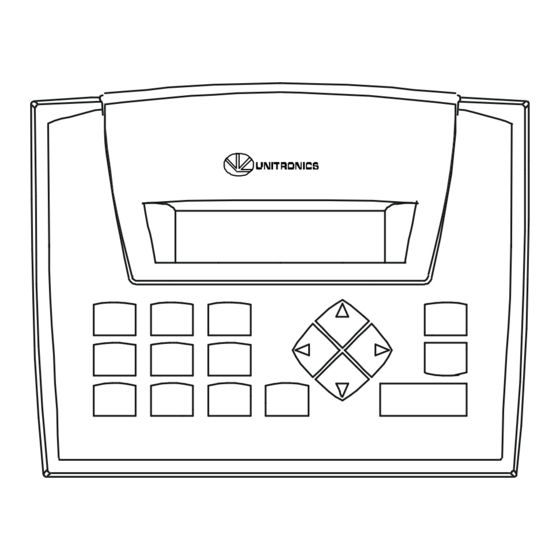
JZ10-11-T40V
Before using this product, the user must read and understand this document.
For additional information regarding this product, refer to the user guide and technical specifications.
All examples and diagrams are intended to aid understanding, and do not guarantee operation.
Unitronics accepts no responsibility for actual use of this product based on these examples.
Please dispose of this product according to local and national standards and regulations.
Only qualified service personnel should open this device or carry out repairs.
Failure to comply with appropriate safety guidelines can cause severe injury or property damage.
Do not attempt to use this device with parameters that exceed permissible levels.
To avoid damaging the system, do not connect/disconnect the device when power is on.
Environmental Considerations
Do not install in areas with: excessive or conductive dust, corrosive or flammable gas,
moisture or rain, excessive heat, regular impact shocks or excessive vibration.
Ventilation: 10mm space required between the controller's top/bottom edges & enclosure walls.
Do not place in water or let water leak onto the unit.
Do not allow debris to fall inside the unit during installation.
Mounting
Dimensions
147.5 mm (5.807")
Add-on modules
Note: Installing an add-on module requires space.
During installation
72 mm (2.835")
Unitronics
Jazz™ Micro-OPLC™ Installation Guide
16 Digital, 2 Analog/Digital, 2 Analog Inputs,
20 Transistor Outputs
12 mm (0.472")
46.6 mm (1.835")
After installation
27.5 mm
(1.083")
113.7 mm (4.476")
13.2 mm (0.52")
Panel mounting
- Cut-out:
117 x 89mm (WxH) 4.606"x 3.504"
- Hold bracket against unit while
tightening screw
Panel
5mm (max)
0.197" (max)
Bracket
Gasket
16.8 mm (0.661")
1
Advertisement
Table of Contents

Summary of Contents for Jazz Micro-OPLC JZ10-11-T40V
- Page 1 Jazz™ Micro-OPLC™ Installation Guide JZ10-11-T40V 16 Digital, 2 Analog/Digital, 2 Analog Inputs, 20 Transistor Outputs Before using this product, the user must read and understand this document. For additional information regarding this product, refer to the user guide and technical specifications.
- Page 2 JZ10-11-T40V DIN-rail mounting Mounting Removal Snap PLC onto the DIN rail Push mounting clip down Note: Removing the unit requires clearance space. Recommendation: approximately 40mm (1.58”). Wiring Note: All diagrams are based on the rear view of the OPLC. Do not touch live wires. Install an external circuit breaker.
- Page 3 JZ10-11-T40V Digital Inputs, Controller’s Power Supply Note: The inputs are arranged in two groups. You can wire one group as npn and the other as pnp, or wire both groups as npn, or as pnp. In either case, the npn/pnp pins must be connected. Input wiring, npn (sink) 24VDC +V 0V...
- Page 4 The tradenames, trademarks, logos and service marks presented in this document, including their design, are the property of Unitronics (1989) (R"G) Ltd. or other third parties and you are not permitted to use them without the prior written consent of Unitronics or such third party as may own them. DIG-JAZZ-T40V 11/11 Unitronics...
Need help?
Do you have a question about the Micro-OPLC JZ10-11-T40V and is the answer not in the manual?
Questions and answers