Advertisement
Quick Links
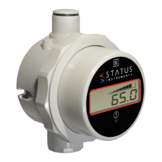
DM650LP USER GUIDE
LOOP POWERED DIGITAL DISPLAY WITH RELAY AND USB/NFC
INTERFACE LOGGING FUNCTION. USER GUIDE
Important - Please read this document before installing.
Every effort has been taken to ensure the accuracy of this document; however, we do
not accept responsibility for damage, injury, loss or expense resulting from errors and
omissions, and we reserve the right of amendment without notice.
IMPORTANT – CE, UKCA & SAFETY REQUIREMENTS.
The instrument is designed to be either directly attached to a sensor probe assembly or
surface mounted. The user must ensure all sensor and cable entries maintain
environmental protection to at least IP65 rating.
Battery - Fire Explosion and Severe Burn Hazard. Do not attempt to re-charge, Crush,
Incinerate, Disassemble, Heat above 100 °C (212 °F) or expose to water.
Disposal of the battery must conform with the regulations applicable for the area
of use.
The product contains no serviceable parts, or internal adjustments. No attempt must be
made to repair this product. Faulty units must be returned to supplier for repair.
This product must be installed by a qualified person. All electrical wiring must be carried
out in accordance with the appropriate regulations for the place of installation.
Before attempting any electrical connection work, please ensure the battery is removed
ABSOLUTE MAXIMUM CONDITIONS: To exceed may cause damage to the
device.
Battery voltage
3.7 Vdc (Protected for reverse connection)
Input current
± 50 mA
Relay
50 Vdc, 40 Vac rms
Ambient
Temperature (-30 to 70) °C,
Humidity (10 to 95) % RH noncondensing)
----------------------------------------------------------------------------------------------------------------------------------------------------------------------------------
1~DESCRIPTION.
The DM650LP loop powered indicator with battery backup accepts a (4 to 20) mA signal
and provides a powerful display interface based on a 6-digit 14-segment LCD display.
User-set scaling is provided to allow the user to set process ranges between -999999
and 999999. Maths functions are provided working on the actual (4 to 20) mA signal for
requirements such as square root extraction.
A 22-segment user-set linearisation/correction function is offered, as well as advanced
messaging, allowing the user to display custom messages for pre-set input ranges.
2~RECEIVING AND UNPACKING.
Please inspect the packaging and instrument thoroughly for any signs of transit
damage. If the instrument has been damaged, please notify your supplier immediately.
3~SPECIFICATION.
Refer to data sheet for full specification.
Configuration
Factory default
(4 to 20) mA = (0 to 100) °C, Relay off
4~ INSTALLATION AND WIRING.
D2610-01-03 CN5819 DM650LP User guide
Important – Read this
document before installing.
4.1~MECHANICAL.
The instrument is a high accuracy digital (4 to 20) mA loop powered display. In order to
ensure correct operation, the following must be observed:
The product must be stored in a dry clean environment and remain in original
packaging prior to installation.
The instrument must not be installed adjacent to electro-mechanical starters,
controllers, thyristor power units or electrical switch gear.
Any cleaning of the instrument must be done using a mild detergent and soft cloth. No
solvents or abrasive cleaners should be used.
Stated ambient operating conditions must not be exceeded. Battery life will reduce with
higher ambient temperature operating conditions.
4.2~ELECTRICAL.
For a wiring diagram please refer to the rear panel of the DM650LP inside the
case housing.
Screw connectors are used for input and relay connections, allowing the unit to be used
with some in head temperature transmitters (refer to sales for details). On insertion of
battery the unit will run through a power-up check; during this time the relay may
change state.
IMPORTANT: Always remove battery before any wiring takes place. Gain access to the
connectors and battery holder by twisting cap to release front panel assembly from
case.
INPUT: The SEM650LP is to be wired in series on a (4 to 20) mA loop. The battery is
not required for basic display operation, however for datalogging operation the battery
will be required. The connections are marked "+" and "-".
RELAY CONNECTION: A relay with changeover contacts is available. Screw terminals
are provided for connection for wire size 16 to 20 AWG. The relay contacts are rated at
48 VDC 28 VAC RMS @ 1 A (5 mA minimum current) see DM650LP data sheet.
The relay connections are marked "NO" for normally open, "NC" for normally closed and
"C" for common.
BATTERY: To remove battery, use screwdriver to ease the positive end of the battery
out of holder. Insert new battery negative end first then press into place. (Observe
polarity). Battery type 3.6 V Lithium (2.4 A/Hr) CR14505 (IEC) AA case style. Please
dispose of the battery in a responsible way.
WARNING
For configuring, reading live data or reading logged data if using a grounded loop on the
input, it is important not to connect the programming USB lead to a mains-powered
computer. It is possible to damage the instrument if connected in this way.
To avoid damage, use one of the following methods:
Disconnect the loop before configuration, reconnect the loop after configuration.
•
Ensure any sensor connected and DM650 housing are not in contact with any
•
conductive parts during configuration.
Use a laptop-type computer running from its battery power supply, not connected
•
to a mains supply. This is recommended for reading lived data or offsetting a unit if
already installed in the field.
Use a USB isolator between the computer and the DM650.
•
5~USER CONFIGURATION.
IMPORTANT READ COMPLETE SECTION BEFORE ATTEMPTING
CONFIGURATION.
The instrument is provided with a USB interface for direct connection to a PC. Free
software USBSpeedLink is available. Please refer to the USBSpeedLink software for
further information on configuration. The software can be downloaded from
www.status.co.uk.
DISPLAY: The display provides six 14-segment characters for display of temperature
and alpha-numeric messages, together with an 8-segment bar graph and six icons. The
display can operate in an ambient temperature range of (-30 to 70) °C, but at
temperatures lower than -5 °C (due to the slower LCD speed) scrolled messaging is not
practical for screen updates.
The display's high contrast, coupled with a digit height of 7.9 mm, offers clear readouts
at low as well as high ambient light and direct sunlight.
The display layout is as follows:
Page 1 of 2
Advertisement

Summary of Contents for Status Instruments DM650LP
- Page 1 16 to 20 AWG. The relay contacts are rated at 48 VDC 28 VAC RMS @ 1 A (5 mA minimum current) see DM650LP data sheet. Battery voltage 3.7 Vdc (Protected for reverse connection) Input current ±...
- Page 2 *Logging and configuration software can be downloaded from www.status.co.uk LIVE DEVICE READING TAB Display Live process value RETRIEVE LOGGED DATA TAB Status Instruments Ltd, Status Business Park, Gannaway Lane, Tewkesbury, Download and graph recorded logged data Gloucestershire, UK, GL20 8FD CONFIGURE LOGGER Web Page: www.status.co.uk, Email: sales@status.co.uk Set new log (rolling or fixed), interval time, number of logs, delay start Technical Support: support@status.co.uk...
Need help?
Do you have a question about the DM650LP and is the answer not in the manual?
Questions and answers