Table of Contents
Advertisement
Quick Links
4TOLB-3L1 4-WIRE, 600-OHM TRANSMISSION ONLY
CONTENTS
1. INTRODUCTION . . . . . . . . . . . . . . . . . . . . . . . 1
A. Reason for Reissue . . . . . . . . . . . . . . . . . . 2
B. Features . . . . . . . . . . . . . . . . . . . . . . . . . . . 3
2. APPLICATIONS . . . . . . . . . . . . . . . . . . . . . . . . 3
3. INSTALLATION AND ALIGNMENT . . . . . . . . . 4
A. Options . . . . . . . . . . . . . . . . . . . . . . . . . . . . 4
B. Connections . . . . . . . . . . . . . . . . . . . . . . . . 7
C. Adjustments . . . . . . . . . . . . . . . . . . . . . . . . 7
4. CIRCUIT DESCRIPTION . . . . . . . . . . . . . . . . 11
A. VF Transmit Operation . . . . . . . . . . . . . . . 11
B. VF Receive Operation . . . . . . . . . . . . . . . 16
C. Loopback Circuit. . . . . . . . . . . . . . . . . . . . 16
5. SPECIFICATIONS . . . . . . . . . . . . . . . . . . . . . 17
6. MAINTENANCE . . . . . . . . . . . . . . . . . . . . . . . 17
7. CUSTOMER SERVICE. . . . . . . . . . . . . . . . . . 20
1. INTRODUCTION
Trademarks used in this manual:
CLEI is a trademark of Bellcore.
Pulsecom is a registered trademark of Hubbell Inc.
SLC is a registered trademark of AT&T.
The Recognized Component Mark is a registered trademark of Underwriters Laboratories Inc.
©1992 Pulse Communications Inc. All rights reserved.
D4 CARRIER SYSTEM
CHANNEL UNIT WITH LOOPBACK
UL RECOGNIZED TELEPHONE EQUIPMENT
CLEI™ Code D4C0P885AA
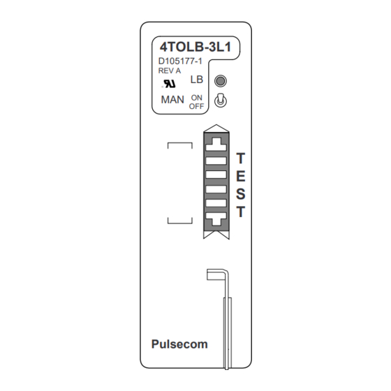
This practice describes the Pulsecom
Channel Unit with Loopback, shown in Figure 1. Installation instructions and engineering
references are included.
PAGE
Figure 1. 4TOLB-3L1 Channel Unit
®
4TOLB-3L1 4-Wire, 600-Ohm Transmission Only
1
Practice Section 1306
Issue 2, May 1992
4TOLB-3L1
D105177-1
REV A
LB
®
ON
MAN
OFF
T
E
S
T
Pulsecom
with Loopback
Advertisement
Table of Contents

Summary of Contents for PULSECOM 4TOLB-3L1
-
Page 1: Table Of Contents
Trademarks used in this manual: CLEI is a trademark of Bellcore. Pulsecom is a registered trademark of Hubbell Inc. SLC is a registered trademark of AT&T. The Recognized Component Mark is a registered trademark of Underwriters Laboratories Inc. -
Page 2: Reason For Reissue
Equipment Reissue The 4TOLB-3L1 differs from the Pulsecom 4TOLB, 4TOLB-2, and 4TOLB-1L3 channel units as shown in Table 1. The 4TOLB-3L1 also provides sealing current with single switch selection of source/sink/off and improved current regulation over loop length in the source mode. -
Page 3: Features
Sealing current source/sink available with power-up ZAP (source mode) • Loopback gain/loss selectable from 0 to 31.75 dB in 0.25-dB steps • Can be used in the Pulsecom PD4 or PSC-96 channel bank • Can be used in the AT&T D4 or SLC 96 channel bank •... -
Page 4: Installation And Alignment
1. When replacing older 4TOLB units, reconnect loopback function leads on the backplane. See Table 1. 2. Use a 325A power converter unit if a 48-channel bank is to be filled with 4TOLB-3L1 plugs. The standard power module may not be able to supply sufficient +12V power. A. Options General The following options provided by the unit allow flexibility of application. - Page 5 4TOLB-3L1 1306, Issue 2, May 1992 Table 2. 4TOLB Switch Options Switch Designation (Note 1) Option Name Function .1 .2 .4 .8 8 16 12 6 3 1.5 .8 .4 .2 .1 RT .25 .5 8 16 Transmit 0.1 dB...
- Page 6 4TOLB-3L1 1306, Issue 2, May 1992 Attenuation Up to 32.5 dB of attenuation in 0.1-dB steps for the TRMT path and up to 24 dB of attenuation in 0.1-dB steps for the RCV path can be selected. TRMT attenuation is selected at switch blocks S1 and S2;...
-
Page 7: Connections
The unit is a Pulsecom Type D4 plug-in module. It occupies a 1.5-inch wide mounting space in a standard Pulsecom PD4, AT&T D4, or equivalent channel bank; see Figure 5A. The unit can also be installed in a Pulsecom PSC-96, AT&T SLC 96, or equivalent channel bank; see Figure 5B. - Page 8 LOOPBACK CONNECTIONS FOR D4 (OR SLC 96 COT) BANK. LOOPBACK CONNECTIONS FOR PSC-96 OR SLC 96 RT BANK. NOTE: MAKE INTERNAL LB CONNECTIONS TO LEADS MARKED EITHER † OR *, BASED ON BANK CONFIGURATION, BUT NOT BOTH. Figure 4. 4TOLB-3L1 Card-Edge Connector Pin Functions...
- Page 9 (24 SUBSCRIBER CHANNELS) SHELF B TWO-SHELF 12 CHANNEL UNITS GROUP (24 SUBSCRIBER CHANNELS) SHELF A B. 4TOLB-3L1 Installed in a Pulsecom PSC-96 or AT&T SLC 96 Channel Bank Figure 5. Location of the 4TOLB-3L1 in Pulsecom or AT&T Channel Banks...
- Page 10 This procedure uses a transmission measuring set (TMS) such as the H.P. 4937A, the front-panel TEST jack of the unit, and MAC jack to bantam jack adapter, such as the Pulsecom B105097 or equivalent. An extender card can be used to provide easy access to...
-
Page 11: Circuit Description
MAC jack on the front panel of the channel unit. The adapter can be the Pulsecom B105097 MAC jack to bantam jack adapter or equivalent. A detailed description of the B105097 is provided in Pulsecom Practice Section 1303. - Page 12 ACTION Plug the B105097 MAC Jack to Bantam Jack Adapter into the TEST jack on the front panel of the near-end 4TOLB-3L1; arrange to have another adapter installed into the TEST jack of the far-end unit. Set the TMS1 in the bridged mode and adjust the TMS1 oscillator output for a 1004-Hz tone at the desired TRMT input level (between +16 dB and –16 dB TLP).
- Page 13 4TOLB-3L1 1306, Issue 2, May 1992 NEAR MODEL 4TOLB-3L1 UNDER TEST MAC TO BANTAM MAC TO BANTAM ADAPTER ADAPTER 0 to 32.5 dB +7.5 TRANSMIT PATH RECEIVE PATH 0 to ±31.75 dB TO/FROM TO/FROM CHAN. BANK CHAN. BANK RECEIVE PATH...
- Page 14 4TOLB-3L1 1306, Issue 2, May 1992 NEAR MODEL 4TOLB-3L1 UNDER TEST DESIRED (LOOPBACK MODE ENABLED) RCV TLP 0 to 32.5 dB NOTE: RCV TLP OUT MUST +7.5 BE SAME AS NEAR END RCV OUT LEVEL IN TEST PART B. BRIDGED...
- Page 15 GATE 2713 Hz DETECT S3 & S4 +4 dB TRANS- ATTN FORMER FILTER 0 to 24 dB NOTE: POWER SUPPLY LEADS ARE NOT SHOWN SHOWS LOOPBACK CONNECTIONS FOR PSC-96 OR SLC 96 RT BANK ONLY. Figure 8. 4TOLB-3L1 Functional Diagram...
-
Page 16: Vf Receive Operation
4TOLB-3L1 1306, Issue 2, May 1992 B. VF Receive Operation At the proper channel time, when the RSP(N), RSQ(N), and RWD leads are all at logic one, the receive sampling gate closes to receive a sample at the receive input port (leads RPAM and RPAMG). -
Page 17: Specifications
In case of equipment malfunction, use the test card (standard AT&T P6AD cord or Pulsecom B105097 adapter) and measurements of input and output signals to determine the trouble source. The TEST jack provides access to the TRMT TLP, the RCV TLP, and the T and R leads;... - Page 18 4TOLB-3L1 1306, Issue 2, May 1992 Table 3. 4TOLB-3L1 Specifications Parameter Condition Value A. Transmission 600 Ω Nominal Impedance T, R and T1, R1 TRMT Input Level a) Nominal –16 dBm b) Range –16 to +16.5 dBm RCV Output Level...
- Page 19 4TOLB-3L1 1306, Issue 2, May 1992 Table 3. 4TOLB-3L1 Specifications (Continued) Parameter Condition Value B. Loopback Parameters Manual LB Activation Via PC Board MAN Switch a) Switch on LB ON b) Switch off LB OFF Tone LB Activation (in RCV Input Port) 2713 ±...
-
Page 20: Customer Service
Questions concerning the operation of the unit can be directed to Pulsecom Customer Service. Pulsecom does not recommend that repairs be performed in the field. Repair services are available and can be obtained by returning the defective unit to the Pulsecom Repair Department.
Need help?
Do you have a question about the 4TOLB-3L1 and is the answer not in the manual?
Questions and answers