Table of Contents
Advertisement
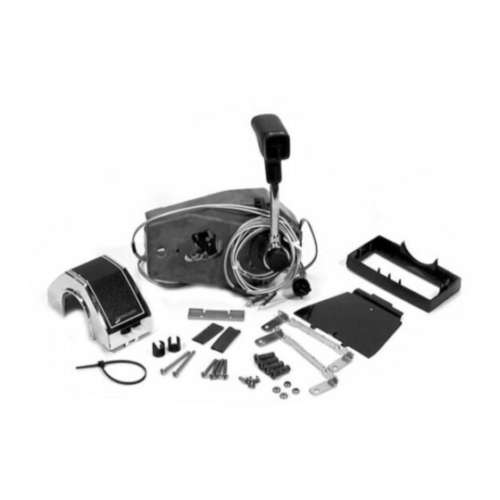
88688A25
SINGLE HANDLE
TRIM CONTROL
INSTALLATION,
OPERATION AND
MAINTENANCE
INSTRUCTIONS
NOTICE to INSTALLER
After Completing Installation, These Instruc-
tions Should Be Placed with the Product For
the Owner' s Future Use.
These installation instructions provide complete in-
formation for installing the remote control. Please read
them carefully and thoroughly before starting installa-
tion.
Printed in U.S.A.
Index
Notice to Installer/Owner ....................... . 2
Maintenance and Replacement Parts ............ . 2
Selecting Remote Control Cables ................ . 2
Introduction ....................................3
Installation . . . . . . . . . . . . . . . . . . . . . . . . . . . . . . . . . . . . . .
Control Module Linkage ..................... . 4
Control Handle .............................. . 4
Repositioning Control Handle .................... 5
Installation .................................. . 7
All Outboard Models thru 250 (3 Litre) .......... . 7
Shift Cable ...................................7
Throttle Cable ............................... . 7
Port Side Control Module Cable Installation ...... . 8
All Outboard Models 35 hp thru 220 hp ....... . 8
Shift Cable .................................. . 8
Throttle Cable ............................... . 8
Required Mounting Clearances . . . . . . . . . . . . . . . . . . . 9
Locating and Drilling Mounting Area . . . . . . . . . . . . . . 9
Remote Control Mounting . . . . . . . . . . . . . . . . . . . . . . . 9
Connections ......................... . 10
Operation. .................................... . 11
2 4 9 0 6
1 -
Page
3
go-812627 l-195
Advertisement
Table of Contents

Summary of Contents for Quicksilver 88688A25
-
Page 1: Table Of Contents
Introduction ........3 88688A25 Installation ........ -
Page 2: Notice To Installer/Owner
OBSERVE THEM CAREFULLY! Marine Lubricant or equivalent. These “Safety Alerts” alone cannot eliminate the 5. Quicksilver throttle and shift control cables recom- hazards that they signal. Strict compliance to these mended for use in this remote control. special instructions when performing the service, plus “... -
Page 3: Introduction
Final Checks and Adjustments Quicksilver throttle and shift control cables are recom- a. Re-check tightness of control handle set screw. mended for use in this remote control. Set screw should be torqued to 60 lb. in. (7 N.m). -
Page 4: Remote Control Alteration For Port Installation
Remote Control Alteration Control Handle for Port Installation Repositioning Control Handle Trim Switch for port control installation. Throttle link and throttle spring must be changed when 1. Pry bezel from handle, pull trim switch out, turn control handle will be positioned on the right side of switch 180”... -
Page 5: Repositioning Control Handle
3. Pull trim switch out from handle and remove wires Repositioning Control Handle from switch. NOTE: Repositioning of control handle (on control shaft) is necessary only if the standard neutral position of control handle is undesirable. IMPORTANT: When repositioning control handle (on control shaft), position handle so that full forward and reverse can be achieved. - Page 6 7. Rotate trim wires and trim wire rotator (on control shaft) to the position that neutral is desired when Control handle set screw must be torqued to specifica- control handle is reinstalled. tion. Failure to tighten set screws securely could allow control handle to disengage, with subsequent loss of throttle shift control.
-
Page 7: Starboard Side Control Module Cable Installation
Starboard Side Control Throttle Cable Module Cable Installation Models 250 (3 All Outboard thru Litre) Before tightening cable fastener locknut, be sure that pin on end of cable fastener is completely thru cable end and shift/throttle lever. A pin, that is partially thru cable and lever, may cause fastener to bend when locknut is tightened. -
Page 8: Port Side Control Module Cable Installation
Throttle Cable Port Side Control Module Cable Installation All Outboard Models thru 250 (3 Litre) Before tightening cable fastener locknut, be sure that pin on end of cable fastener is completely thru cable end and shift/throttle lever. A pin, that is partially thru cable and lever, may cause fastener to bend when locknut is tightened. -
Page 9: Required Mounting Clearances
Required Mounting Clearance 1. Insert wellnut fasteners into dr lled holes with flange against the outer surface. (Metric: 1” = 25.4mm) NOTE: It may be helpful to thread a mounting screw into fastener when inserting fastener into drilled hole. Mounting Screw 111) Mounting Surface Wellnut 2. -
Page 10: Electrical Connections
6. Install cover on remote control by snapping into Route control cables and wiring harnesses thru place. mounting base, then place remote control into posi- tion on mounting base. Electrical Connections Failure to connect neutral start safety switch leads 50128 properly could allow engine to start while in gear. -
Page 11: Operation
Operation Check that water level is above water intake ports. Control Handle: Features full gear shift and throttle. (Should water level fall below water intake ports, dam- Shift into gear with a firm, quick motion. Do not age from overheating or water pump impeller damage ease gears into or out of engagement. - Page 12 Template for Dual and Single Console Controls Outline of Remote Control Cover for Dual Control Centerline for Sing le Control - - - 3/8” Dia. for Dual Control 3/8” (9.53mm) Dia. for Single Control Outline of Remote Control Cover for Single Control 1/4”...
Need help?
Do you have a question about the 88688A25 and is the answer not in the manual?
Questions and answers
does this controller take gen 1 cables 88688A25
Yes, the Quicksilver 88688A25 controller uses Gen I cables.
This answer is automatically generated