
Subscribe to Our Youtube Channel
Summary of Contents for Douglas Lighting Controls WRS-2224
- Page 1 WRS-2224 Programmable Relay Scanner Instruction Manual DOUGLAS lighting controls...
-
Page 2: Table Of Contents
Setup: Flick Warn Option ......................8 Setup: Time Out Option ......................9 Connections: Stand Alone Panels ..................10 Connections: Multiple Panels ....................12 Troubleshooting ........................14 Appendix A -Input/Output Log ....................15 Notes ..........................16 DOUGLAS lighting controls WRS-2224: Directions & Applications... -
Page 3: Introduction
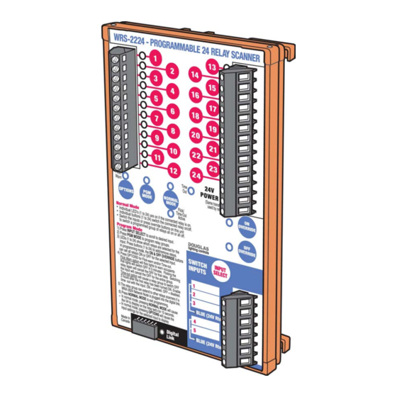
WRS-2224 Programmable Relay Scanner The WRS-2224 Scanner can be programmed so that when an input is signalled ON or OFF, it switches a specific group of output relays ON or OFF. The WRS-2224 has 5 inputs and 24 relay outputs. -
Page 4: Parts And Dimensions
1.75" 4.0" (45 mm) (103 mm) Side View Plan View · Relay Scanners mount to 35mm DIN rail installed in relay panels. · Each unit is shipped with DIN mounting rail. DOUGLAS lighting controls WRS-2224: Directions & Applications page 2... -
Page 5: Specifications
Relay outputs are isolated from each other. The pulse of a local switch connected to a relay on an output will not pass through the scanner to a relay connected on another output. DOUGLAS lighting controls page 3 WRS-2224: Directions & Applications... -
Page 6: Installation
Contacts (no Diodes) momentary contacts. the WR-8001 rocker switch which is NOT OK with maintained · Inputs for the WRS-2224 can also be configured to able to select an ON or OFF signal. contacts. accept 24V signals that have no diode connected. -
Page 7: Basics: Normal Mode/Version Number
1. Make sure the individual relays are properly connected to the output terminals. 2. The WRS-2224 Scanner will usually be in NORMAL mode. If left in PROGRAM mode, it will revert to NORMAL mode after 2 minutes. If the NORMAL MODE indicator LED is OFF, press its select button to exit the PROGRAM mode. -
Page 8: Setup: Input Configuration Mode
Rectified AC Pulse. No current for Indicator LEDs. (23) - Positive=OFF / Negative=ON NOTE: LED switches will not function properly with this configuration. Table 1. Switch Hardware Type DOUGLAS lighting controls page 6 WRS-2224: Directions & Applications... -
Page 9: Setup: Program Mode
OFF OVERRIDE button. NOTE: If there is 2 minutes of inactivity during PROGRAM mode, the scanner will revert to NORMAL mode. To return to PROGRAM mode, press the PROGRAM MODE selectbutton. DOUGLAS lighting controls WRS-2224: Directions & Applications page 7... -
Page 10: Setup: Flick Warn Option
(HID lights require more than 5 minutes to turn ON after being turned OFF.) 3. Press the OPTIONS button (usually 3 times) so that both the FLICK WARN LED and TIME OUT LED are OFF. 4. Return to NORMAL mode. DOUGLAS lighting controls page 8 WRS-2224: Directions & Applications... -
Page 11: Setup: Time Out Option
It will be necessary, in that case, to shut off and restart the Relay Scanner, and then re-program all of the input groups with only one all-inclusive group assigned TIME OUT. S e n s o r S e n s o r DOUGLAS lighting controls page 9 WRS-2224: Directions & Applications... -
Page 12: Connections: Stand Alone Panels
NW Priv Office Group NW Priv Office Switch WTP-4408 Station Time Clock Quad Quad Quad Quad Core S e n s o r S e n s o r Core Core 24VAC Power DOUGLAS lighting controls page 10 WRS-2224: Directions & Applications... - Page 13 Connections: Stand Alone Panels Simple Stand Alone Panels The WRS-2224 Programmable Relay Scanner permits a group of relays to be controlled with a single switch. The scanner can support up to 5 groups of relays, each controlled by one of 5 switch inputs.
-
Page 14: Connections: Multiple Panels
N o r m a l M o d e As all Douglas scanners have optically-isolated master switch inputs, the WRS-2224 Relay Scanner in the panel will isolate the power in the bus signal from the power used in the panel... - Page 15 Another method of interconnecting load centers/relay panels is to use the Douglas WNX-2624 Network Node. With the WNX-2624 Node, you can network the WRS-2224 Programmable Relay Scanner with a non- polarized data signal to other WRS-2224 Relay Scanners. Up to twenty-four WRS-2224/WNX-2624 scanner/node combinations can exist within a self-configured system.
-
Page 16: Troubleshooting
Relay group not programmed properly TIME OUT assigned to more than one group - assign TIME OUT only to one all-inclusive group Table 2. WRS-2224 Troubleshooting Guide DOUGLAS lighting controls WRS-2224: Directions & Applications page 14... -
Page 17: Appendix A -Input/Output Log
Appendix A - Input/Output Log Date Output Relays Input Switches Input Remarks Type Remarks Remarks Type Remarks Remarks Remarks Type Remarks Remarks Remarks Remarks Type Remarks Remarks Type Remarks Remarks Remarks Additional Remarks: DOUGLAS lighting controls WRS-2224: Directions & Applications page 15... -
Page 18: Notes
Notes DOUGLAS lighting controls page 16 WRS-2224: Directions & Applications... - Page 19 Notes DOUGLAS lighting controls page 17 WRS-2224: Directions & Applications...
- Page 20 4455 Juneau Street • Burnaby, B.C. • CANADA DOUGLAS lighting controls reserves the right to cancel or phone: (604) 873-2797 • fax: (604) 873-6939 change items shown in this publication without notice.
Need help?
Do you have a question about the WRS-2224 and is the answer not in the manual?
Questions and answers