Advertisement
Quick Links
1
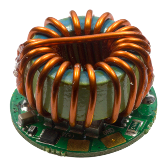
PCB Components
U
M
SER
ANUAL
www.ledtreiber.de
Contens ................................................................................................................................................. 1
Overview and Features of the Senser Xtreme ...................................................................................... 2
PCB layout / Installation ....................................................................................................................... 3
Dimming with PWM ............................................................................................................................. 4
Leds, voltages, currents ..................................................................................................................... 5-7
Dimensions, temperature sensor, increase output current to 3A (applies to version 1) .................. 8-9
© PCB Components • v2.3
Advertisement

Subscribe to Our Youtube Channel
Summary of Contents for PCB Components Senser Xtreme
- Page 1 PCB Components ANUAL www.ledtreiber.de Contens ..............................1 Overview and Features of the Senser Xtreme ..................2 PCB layout / Installation ........................3 Dimming with PWM ..........................4 Leds, voltages, currents ........................5-7 Dimensions, temperature sensor, increase output current to 3A (applies to version 1) ....8-9...
- Page 2 Overview and Features The Senser Xtreme R.2 is the complement to our proven Senser V2. It is a very powerful boost constant current source that sets new standards. The (input) current can be up to 8 amps, so you can already operate with very low input voltage, a large number of LED's with high currents.
- Page 3 50/50%, but by the fluctuations of a typical diode, the LED current is distributed in such two parallel lines is not exactly 50/50%. If in a parallel connection one strand lose, the current is distributed to the remaining (n) Led strands. © PCB Components • v2.3...
- Page 4 Make sure in your application on any adjacent batteries! Dimming with PWM: The Led Senser Xtreme has an external input on what you can dim with a pulse width modulation signal. To the PWM-pad, a PWM signal with a recommended frequency of about 200Hz-10000Hz can be connected.
- Page 5 P (10V) P (13V) P (16V) P (19V) P (22.5V) P (25.5V) 6.5V P (28.5V) 6.5V P (30V) 6.5V P (30V) 6.5V P (30V) 6.5V P (30V) 6.5V P (30V) 6.5V P (30V) 6.5V P (30V) © PCB Components • v2.3...
- Page 6 Min. Volt P (7.5V) P (10.5V) P (14V) P (17.5V) 6.5V P (20.5V) P (24V) P (27V) 7.5V P (30V) P (30V) 8.5V P (30V) P (30V) P (30V) P (30V) 11.5V P (30V) P (30V) © PCB Components • v2.3...
- Page 7 P (7.5V) P (11V) 6.7V P (14.5V) 6.7V P (18V) P (21V) P (24.5V) P (28V) P (30V) P (30V) P (30V) P (30V) 14V/17V* P (30V) 15V/23V* P (30V) 16V* P (30V) 17V* P (30V) © PCB Components • v2.3...
-
Page 8: Important Note
If the driver is operated at voltages below 6.5V, make sure that the input current does not rise above 5A. If battery supply is used, it must switch off at the latest at 6V to avoid damage to the driver! © PCB Components • v2.3... - Page 9 The 200mA bridge acts as a 1.2A bridge now. To get 3 Ampere, all solderbridges are closed. The needed resistors we can deliver. We tested this setting with up to 8 pcs. Led at 3 Ampere. © PCB Components • v2.3...
Need help?
Do you have a question about the Senser Xtreme and is the answer not in the manual?
Questions and answers