
Related Manuals for PowerWave G3L-1929-160


Summary of Contents for PowerWave G3L-1929-160
- Page 1 G3L-1929-160 Multi-Carrier Power Amplifier Installation and Service Manual 044-05237 Rev A June 2006...
- Page 2 © 2006 Powerwave Technologies Incorporated. All rights reserved. Powerwave Technologies, and the Powerwave logo are registered trademarks. This Powerwave product is intended only for installation in a RESTRICTED ACCESS LOCATION and this Powerwave product is designed to operate within the normal operating (typical operating) ranges or conditions specified in this document.
- Page 3 Warnings, Cautions, and Notes Warnings, Cautions, and Notes are found throughout this manual where applicable. The associated icons are used to quickly identify a potential condition that could result in the consequences described below if precautions are not taken. Notes clarify and provide additional information to assist the user. WARNING: This warning symbol means danger.
- Page 4 Revision Record Revision Letter Date of Change Reason for Change June 2006 Initial Release 044-05237 Rev A...
-
Page 5: Table Of Contents
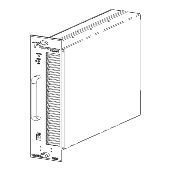
Table of Contents Chapter 1 - Product Description 1.1 Introduction..............1-1 1.2 Scope of Manual. - Page 6 GL3-1929-160 MCPA List of Figures List of Figures Figure 1-1 MCPA Front and Rear Isometric Views ......... .1-2 Figure 1-2 MCPA Functional Block Diagram.
-
Page 7: Chapter 1 - Product Description
Product Description Introduction This manual contains information and procedures for the installation, operation, and maintenance of the G3L-1929-160 Multi-Carrier Power Amplifier (MCPA). Scope of Manual This manual is intended for use by service technicians familiar with similar types of equipment. It contains service information required for the equipment described and is current as of the printing date. - Page 8 Functional Description G3L-1929-160 MCPA Rear Front Figure 1-1 MCPA Front and Rear Views 044-05237 Rev A...
-
Page 9: Preamplifier
G3L-1929-160 MCPA Functional Description FIRST LOOP SECOND LOOP Pilot Tone First Loop Premain Main Delay RF Out Phase and Gain Filter Amplifier Amplifier RF Sample Pilot Tone Generator Error Error Out Second Loop RF In Preamp Delay Amplifier Phase and Gain... -
Page 10: Feed-Forward Loop Control Circuits
Cooling G3L-1929-160 MCPA 1.4.3 Feed-forward Loop Control Circuits The primary function of the first loop is to amplify the carrier signals and isolate an error signal for the second loop. It does this by amplifying the carrier signals and isolating an error signal which is passed to the second loop. -
Page 11: Power Distribution
G3L-1929-160 MCPA Power Distribution Power Distribution The host system provides +26 to 28 VDC power for the MCPA. The DC/DC converter and voltage regulator in the MCPA converts the +27 VDC to +15 VDC, +9 VDC, +5 VDC, and -5 VDC for internal use. - Page 12 Power Distribution G3L-1929-160 MCPA This page intentionally left blank. 044-05237 Rev A...
-
Page 13: Chapter 2 - Controls And Indicators
Chapter 2 Controls and Indicators Introduction This chapter contains descriptions of the G3L-1929-160 Multi-Carrier Power Amplifier (MCPA) controls and indicators. MCPA Controls and Indicators The location of the MCPA controls and indicators are illustrated in Figure 2-1 and listed with descriptions in Table 2-1. -
Page 14: Table 2-1 Mcpa Controls And Indicators
MCPA Controls and Indicators G3L-1929-160 MCPA Table 2-1 MCPA Controls and Indicators Controls and Indicators Description Toggle Switch, Three Position MCPA RESET (Up) Resets . LED indicates boot mode (red), then turns solid green ON (Center) Enables MCPA. LED indicates solid green OFF (Down) Disables MCPA. -
Page 15: Mcpa Connectors
G3L-1929-160 MCPA MCPA Controls and Indicators Table 2-2 MCPA Alarm States (Continued) Alarm Definition Alarm type/LED Auto-Recovery Exceed Disables MCPA immediately if Major Auto-recovery when supply voltage Maximum supply DC voltage > +30.5 VDC. (Red) drops to < +29.5 VDC. -
Page 16: Table 2-3 Mcpa Connector Pinouts
MCPA Controls and Indicators G3L-1929-160 MCPA Table 2-3 MCPA Connector Pinouts Function Function RF Input (Coaxial Contact) Summary_Fault +27 VDC (Power Contact) DC (On/Off) Ground (Power Contact) System Reset TTL RF Output (Coaxial Contact) TX_H (RS-485) TX_L (RS-485) AMP AO... -
Page 17: Chapter 3 - Installation
Chapter 3 Installation Introduction This chapter contains unpacking, inspection, startup and installation procedures for the G3L-1929- 160 Multi-Carrier Power Amplifier (MCPA). • Review this chapter prior to equipment installation. • Review any government and local codes applicable to this installation. •... -
Page 18: Table 3-2 Mcpa Installation
MCPA Installation Instructions G3L-1929-160 MCPA The modular MCPA can be installed in a variety of systems. All system connections to the MCPA are made through the MCPA rear connector, no additional wiring is required. Perform the steps in Table 3- 2 to install the MCPA. -
Page 19: Initial Start-Up And Operating Procedures
G3L-1929-160 MCPA Initial Start-up and Operating Procedures Initial Start-up and Operating Procedures Perform the MCPA initial start-up per the instructions in Table 3-3. CAUTION: Before applying power, ensure input and output cables are properly terminated at the Duplexer front panel. Do not operate MCPA without a load attached. Excessive input power may damage the MCPA. - Page 20 Initial Start-up and Operating Procedures G3L-1929-160 MCPA This page intentionally left blank. 044-05237 Rev A...
-
Page 21: Chapter 4 - Maintenance
Chapter 4 Maintenance Introduction This chapter contains instructions for periodic maintenance, testing and troubleshooting for the G3L- 1929-160 Multi-Carrier Power Amplifier (MCPA). Periodic Maintenance NOTE Check your sales order and equipment warranty before attempting to service or repair unit. Do not break seals on equipment under warranty or warranty will be null and void. Do not return equipment for warranty or repair service until proper shipping instructions are received from factory. -
Page 22: Return For Service Procedures
Insert MCPA into subrack. Turn quarter-turn fasteners to locked position to secure MCPA. Return For Service Procedures When returning products to Powerwave, the following procedures will ensure optimum response. 4.6.1 Obtaining An RMA A Return Material Authorization (RMA) number must be obtained prior to returning equipment and to reduce delays in receiving repair service. -
Page 23: Multi-Carrier Power Amplifier Specifications
Chapter 5 Specifications Multi-Carrier Power Amplifier Specifications The performance and physical specifications for the G3L-1929-160 MCPA are listed in Table 5-1. Table 5-1 MCPA Specifications Electrical Specifications/Features Operating Frequency Band 1930-1990 MHz Instantaneous Bandwidth 40 MHz Air Interface GSM, EDGE, CDMA, W-CDMA... - Page 24 Multi-Carrier Power Amplifier Specifications G3L-1929-160 MCPA Table 5-1 MCPA Specifications (Continued) Mechanical Specifications/Features Controls Three position toggle switch: OFF/ON/RESET. Alarm Indication LED; Green (normal), Yellow (minor alarm), Red (Major alarm). Platform Compatibility Everest Power Amplifier (PA) will reduce power level to Harley/Python APC levels if placed in a Harley/Python subrack.
- Page 25 Tel: +852 2512 6123 Fax: +46 8 540 823 40 Fax: +852 2575 4860 ©Copyright 2006, Powerwave Technologies, Inc. All Rights reserved. Powerwave, Powerwave Technologies, The Power in Wireless and the Powerwave logo are registered trademarks of Powerwave Technologies, Inc.
Need help?
Do you have a question about the G3L-1929-160 and is the answer not in the manual?
Questions and answers