Table of Contents
Advertisement
Quick Links
Advertisement
Table of Contents

Related Manuals for Warehouse AL01P01


Summary of Contents for Warehouse AL01P01
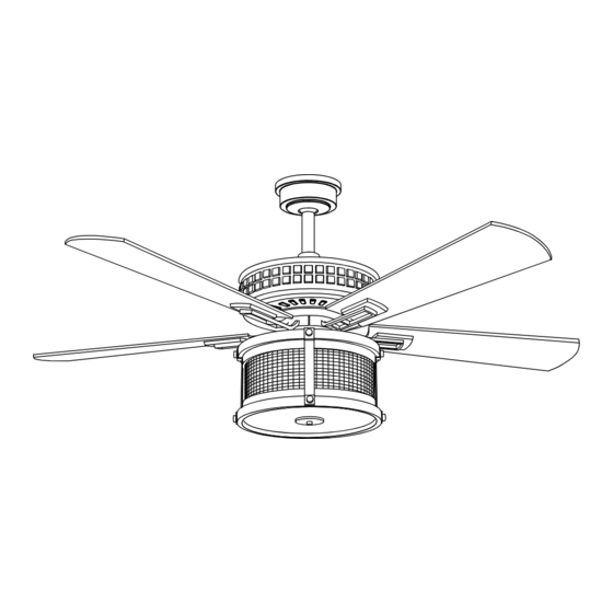
- Page 1 USE AND CARE GUIDE 52 INCH CEILING FAN AL01P01...
-
Page 2: Table Of Contents
Table of Contents Table of Contents ..........2 Assembly..........8 Assembly—Hanging the fan..9-10-11-12 Safety Information ..........3 Operation..........13-14 Warranty ..............4 Pre-Installation............4 Care and Cleaning........14 Pre-Installation(continued) ........5 6 Troubleshooting........15 Installation.............7... -
Page 3: Safety Information
Safety Information READ AND SAVE THESE INTSTRUCTIONS 1. To reduce the risk of electric shock, ensure the electricity WARNING: To Reduce The Risk Of Personal Injury,Do Not has been turned off at the circuit breaker or fuse box Bend The Blade Brackets When Installing The Brackets, before Attempting installation. -
Page 4: Warranty
Warranty The supplier warrants the fan motor to be free from defects in workmanship and material present at time of shipment from the factory for a lifetime after the date of purchase by the original purchaser. The supplier warrants that the light kit, excluding any glass, to be free from defects in workmanship and material at the time of shipment from the factory for a period of three years after the date of purchase by the original purchaser. - Page 5 Pre-Installation (continued) HARDWARE INCLUDED NOTE: Hardware not shown to actual size . Quantity Description Part Blade attachment hardware Screws (preassembled) Clevis pin (preassembled) Cotter pin (preassembled) Extra blade bracket hardware CR2032 aneroid battery3V Expansion bolt(not to scale) Hanger bracket mounting screws(not to scale)
-
Page 6: Pre-Installation(Continued)
Pre-Installation (continued) PACKAGE CONTENTS SG-A10 Description Part Description Part Quantity Quantity Mounting bracket (preassembled) Blade bracket (flange), screws pre-installed Toughened glass Hanger ball/downrod assembly Receiver Canopy Remote control Coupling ring(preassembled) Coupling cover Remote control holder Fan-motor assembly Metal tapping washer Light kit Finial Blade... -
Page 7: Installation
Installation MOUNTING OPTIONS WARNING: To reduce the risk of fire, electric shock, or NOTE: You may need a longer downrod to maintain proper personal injury, mount the fan to an outlet box marked blade clearance when installing on a steep, sloped ceiling. acceptable for fan support using the screws provided with the The maximum angle allowable is 18°... -
Page 8: Assembly
Assembly 1.Install the suspension system components 1. Insert the ball/downrod (B) through the canopy(C) and canopy bottom cover (D), and then slide the decorative motor collar cover (E) onto the end of the ball/downrod(B). Make sure the slots on the canopy (C) are on top. 2.Assembling the fan WARNING: Failure to properly install the locking pin could result in the fan becoming... -
Page 9: Assembly-Hanging The Fan
Assembly— Hanging the Fan 3.Description of mounting bracket 1.Lossen the two outlet boxscrews in the WARNING: To reduce the risk of fire,electric shock or other outlet box. personal injury, mount the fan only to an outlet box or Supporting system marked acceptable for fan support and 2.Pass the 120-Volt supply wires through use the mounting screws provided with the outlet box. - Page 10 Assembly— Hanging the Fan (continued) 4. Hanging the fan to the mounting bracket WARNING: to reduce the risk of electric shock, please operate after starting to disconnect the power supply of circuit breakeror fuse box. 1. Carefully lift the fan motor assembly (F)up to the mounting bracket (A) and seat the hanger ball/downrod assembly(B) in the mounting bracket (A) socket.
- Page 11 Assembly— Hanging the Fan (continued) 7. Making the electrical connections WARNING: Check to gee that all connections are tight, WARNING: To avoid possible electrical shock, turn the including ground,and that no bare wire is visible at the electricity off at the main fuse box before wiring. If you connect Terminal blocks, except for the ground wire.
- Page 12 Assembly— Hanging the Fan (continued) 8.Attaching the light kit fitter assembly and the bulbs WARNING WARNING: to reduce the risk of electric shock, please E12 the light bulb, operate after starting to disconnect the power supply of MAX 40W TYPE B BULB*2PCS circuit breakeror fuse box.
-
Page 13: Operation
Operation REMOTE CONTROL OPERATING INSTRUCTIONS 1.Fan function Press and release the button to tum the fan on or off. Fan off. The fan memory function will store the current setting for the next time the fan is in use. 2.Speed functions Press+ to increase the desired speed of the fan from low, medium, high. -
Page 14: Care And Cleaning
Operation (continued) REVERSE SWITCH OPERATING INSTRUCTIONS The reverse switch is located on the top of the motor housing. Slide the switch to the right for warm weather operation. Slide the switch to the left for cool weather operation. NOTE: Wait for the fan to stop before reversing the direction of the blade rotation. -
Page 15: Troubleshooting
Troubleshooting WARNING: Make sure the power is off at the electrical panel box before you attempt any repairs. Refer to step 6"Making the electrical connections" on page 11. Problem Solution Check the main and branch circuit fuses or breakers. Check the line wire connections to the fan and switch wire connections in the switch housing The fan will not start Check to make sure the frequency switches from the remote control and receiver are set to the same frequency.
Need help?
Do you have a question about the AL01P01 and is the answer not in the manual?
Questions and answers