Table of Contents
Advertisement
Quick Links
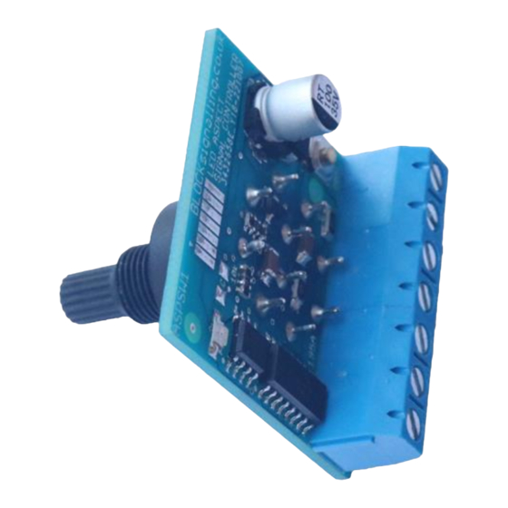
SIGNAL CONTROL SWITCH ASPSW1
The ASPSW1 is used to manually operate multi-aspect led signals from a control
panel position using a rotary switch. Matching panel mounting kits containing legend
plates, control knobs and screws are available separately.
The lit aspects to be shown by the attached led signal can be selected using a
rotary knob at the control panel
When moving through positions with the switch, signal changes are
supressed until a final selection is made
All changes to the aspects shown by the signal are made using progressive
fading to simulate the use of filament lamps in the signal (can be turned off).
Additional leds can be fitted to the control panel to mimic those on the layout.
No resistors are required simplifying wiring as the module provides a stable
output to feed the attached signal
Requires a 12V DC Power Supply
Advertisement
Table of Contents

Summary of Contents for BLOCKsignalling ASPSW1
- Page 1 SIGNAL CONTROL SWITCH ASPSW1 The ASPSW1 is used to manually operate multi-aspect led signals from a control panel position using a rotary switch. Matching panel mounting kits containing legend plates, control knobs and screws are available separately. The lit aspects to be shown by the attached led signal can be selected using a rotary knob at the control panel ...
-
Page 2: Power Supply
The ASPSW1 overcomes all of these problems and provides simple operation of the attached signal with a control which is in keeping with the types of switches provided in signal boxes. -
Page 3: Connecting Signals
BLOCKsignalling www.blocksignalling.co.uk Connecting Signals The power supply and signal connections are made to the screw terminals on the rear of module. YELLOW GREEN YELLOW BLUE WIRE (TOP YELLOW LED +) GREEN WIRE (GREEN LED +) POWER YELLOW WIRE (LOWER YELLOW LED +) - Page 4 Legend Plate Kits Currently available legend plates are 50mm x 50mm (approx. 2” square). The ASPSW1 module is fixed to the rear of the plate and held in place by the shaft of the rotary switch. Align the small tang of the switch with the left hole on the legend plate.
-
Page 5: Drilling Template
BLOCKsignalling www.blocksignalling.co.uk Assembly Side View 16.5mm 10.5mm Knob BLOCK signalling ASPSW1 Baseboard Legend Plate Drilling Template 21.5mm 21.5mm 25mm Central hole >18mm Corner holes 2.5mm Page 5 of 11... - Page 6 BLOCKsignalling www.blocksignalling.co.uk Example Control Panel The diagram below shows an example of a control panel with the ASPSW1 module mounted below the route mimic. The module has been fitted with a control panel legend plate and control knob. As well as the attached signal, “repeater” leds can be fitted to the control panel and wired to the module so the status of any signal out of view of the operator can be confirmed.
- Page 7 BLOCKsignalling www.blocksignalling.co.uk Control Panel Led Wiring The diagram below shows the additional wiring connections for optional control panel leds. YELLOW GREEN YELLOW BLUE WIRE (TOP YELLOW LED +) GREEN WIRE (GREEN LED +) POWER YELLOW WIRE (LOWER YELLOW LED +)
- Page 8 BLOCKsignalling www.blocksignalling.co.uk Programming There is no necessity to reprogram the module, but there are a small number of adjustments available to the user to change how the module operates. Programming is performed by holding down the Push Button when switching on the power and counting flashes of the led on the board..
-
Page 9: Factory Reset
BLOCKsignalling www.blocksignalling.co.uk Program Flow Diagram As mentioned above, there are a number of memory locations which can programmed with different values to change the operation of the module. Before starting, it is a good idea to write down the memory locations and the values you are going to set them to. - Page 10 BLOCKsignalling www.blocksignalling.co.uk 1=SELECT APPLY POWER FACTORY RESET 1=PERFORM RESET 1=LAMP TEST 2=SELECT MODE 2-ASPECT SIGNALLING 3-ASPECT SIGNALLING 4-ASPECT SIGNALLING 7=SET LAMP 1=SLOW 9=FAST FADE DOWN RATE DEFAULT=3 8=SET LAMP 1=SLOW 9=FAST FADE UP RATE DEFAULT=4 10=SET MAX RED SET MAXIMUM BRIGHNESS...
-
Page 11: Troubleshooting
Align the knob with the most anticlockwise legend, and push the control knob back into place. Q. How many ASPSW1 modules can I power from my 12V DC power supply ? A. The module consumes less than 0.02A (20mA), so with a 1A power supply it should comfortably be possible to operate 50 or more modules.
Need help?
Do you have a question about the ASPSW1 and is the answer not in the manual?
Questions and answers