Table of Contents
Advertisement
Quick Links
Pmod CMPS2™ Reference Manual
Revised July 19, 2017
This manual applies to the Pmod CMPS2 rev. A
Table of Contents
Table of Contents .................................................................................................................. 1
Overview ............................................................................................................................... 2
1
Specifications ................................................................................................................. 2
1.1
Pinout Table Diagram ....................................................................................................... 3
1.2
Physical Dimensions ......................................................................................................... 3
2
Functional Description ................................................................................................... 3
2.1
Serial Communication ...................................................................................................... 3
2.2
Register Details ................................................................................................................. 3
2.2.1
2.2.2
2.2.3
2.2.4
2.2.5
2.3
Quick Start ........................................................................................................................ 5
2.4
Applications Information.................................................................................................. 7
2.4.1
2.4.2
2.5
Timing Diagrams ............................................................................................................. 12
DOC#: 410-355
Arrow.com.
Downloaded from
Data Registers ........................................................................................................... 3
Status Register .......................................................................................................... 4
Internal Control Registers ......................................................................................... 4
Continuous Measurement Mode.............................................................................. 5
Output Resolution Measurement Time .................................................................... 5
Calibration ................................................................................................................. 7
Data Conversion ...................................................................................................... 11
Copyright Digilent, Inc. All rights reserved.
Other product and company names mentioned may be trademarks of their respective owners.
1300 Henley Court
Pullman, WA 99163
509.334.6306
www.store. digilent.com
Page 1 of 12
Advertisement
Table of Contents

Related Manuals for Digilent Pmod CMPS2

Summary of Contents for Digilent Pmod CMPS2
-
Page 1: Table Of Contents
Pullman, WA 99163 509.334.6306 www.store. digilent.com Pmod CMPS2™ Reference Manual Revised July 19, 2017 This manual applies to the Pmod CMPS2 rev. A Table of Contents Table of Contents ........................1 Overview ..........................2 Specifications ......................... 2 Pinout Table Diagram ....................... 3 Physical Dimensions ...................... -
Page 2: Overview
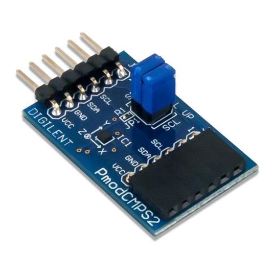
Pmod CMPS2™ Reference Manual Overview The Digilent Pmod CMPS2 is a 3 axis anisotropic magneto-resistive sensor. With Memsic's MMC34160PJ, the local magnetic field strength in a ±16 Gauss range with a heading accuracy of 1° and up to 0.5 mG of resolution. -
Page 3: Pinout Table Diagram
0110000 and then a read/write bit (high/low logic level, respectively), followed by the register address of interest at a maximum clock frequency of 400 kHz users can both configure and read from the Pmod CMPS2. An additional set of pins on header J2 is provided so that users may daisy chain the Pmod CMPS2 with other I²C devices. -
Page 4: Status Register
Continuous Measurement Mode Mode Take Measurement 0¹ Setting this bit will initiate a reading Copyright Digilent, Inc. All rights reserved. Page 4 of 12 Other product and company names mentioned may be trademarks of their respective owners. Arrow.com. Arrow.com. Arrow.com. Arrow.com. -
Page 5: Continuous Measurement Mode
1.20 mS Quick Start Here is the series of commands to acquire a set of magnetometer data from the Pmod CMPS2 via pseudo I²C code. 1. Power on the Pmod CMPS2 and wait for 10 mS before further operation. 2. Provide a START condition and call the device ID with a write bit Copyright Digilent, Inc. - Page 6 6. Write the command to take a measurement by setting bit 0 high followed by a STOP bit. I2CWrite(0x01); //0x01 initiates a data acquisition 7. Delay at least 7.92 mS by default to allow the Pmod CMPS2 to finish collecting data. 8. Provide a START condition and call the device ID with a write bit I2CBegin(0xA0);...
-
Page 7: Applications Information
21. Wait 1/3 of the acquisition time (by default 2.64 ms) before performing another measurement. Applications Information The Pmod CMPS2 is an ideal Pmod to use as a compass. Like all compasses, it is recommended that the Pmod CMPS2 is calibrated before using the module. - Page 8 20. Write the command to take a measurement by setting bit 0 high followed by a STOP bit. I2CWrite(0x01); //0x01 initiates a data acquisition 21. Delay at least 7.92 mS by default to allow the Pmod CMPS2 to finish collecting data. 22. Provide a START condition and call the device ID with a write bit I2CBegin(0xA0);...
- Page 9 I2CWrite(0x40); //0x40 starts the RESET action 48. Wait to receive an ACK from the Pmod CMPS2. 49. Delay at least 1 mS to allow the Pmod CMPS2 to finish the SET action. Copyright Digilent, Inc. All rights reserved. Page 9 of 12 Other product and company names mentioned may be trademarks of their respective owners.
- Page 10 54. Write the command to take a measurement by setting bit 0 high followed by a STOP bit. I2CWrite(0x01); //0x01 initiates a data acquisition 55. Delay at least 7.92 mS by default to allow the Pmod CMPS2 to finish collecting data. 56. Provide a START condition and call the device ID with a write bit I2CBegin(0xA0);...
-
Page 11: Data Conversion
SET and RESET actions. The advantage of this method is when the Pmod CMPS2 is continually changing locations or when other external magnetic fields may be introduced into the test environment. -
Page 12: Timing Diagrams
If D is between 0 degrees and 67.5 degrees – North-East Timing Diagrams An example timing diagram for reading and writing to the Pmod CMPS2 taken from the Memsic datasheet is provided below: When using an external power supply to run the Pmod, be sure to stay within the parameters provided in Specifications.
Need help?
Do you have a question about the Pmod CMPS2 and is the answer not in the manual?
Questions and answers