Advertisement
Available languages
Available languages
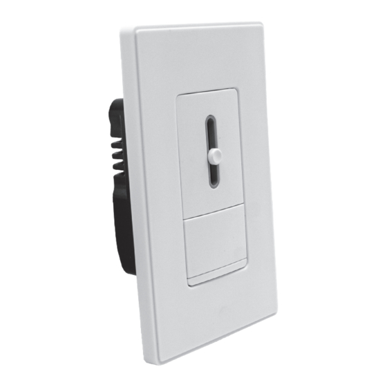
USER MANUAL
SINGLE-POLE / 3-WAY
SLIDE DIMMER SWITCH
120VAC, 60Hz Incandescent 600W,
APPLICABLE MODEL #140180
WARNINGS AND CAUTIONS
1. WARNINGS: TO AVOID FIRE, SHOCK, OR DEATH, TURN OFF POWER AT CIRCUIT BREAKER OR
FUSE AND TEST THAT THE POWER IS OFF BEFORE WIRING!
2. CAUTION: TO REDUCE THE RISK OF OVERHEATING AND POSSIBLE DAMAGE TO OTHER
EQUIPMENT, DO NOT INSTALL TO CONTROL A RECEPTACLE, A MOTOR OPERATED APPLIANCE,
A FLUORESCENT LIGHTING FIXTURE, OR A TRANSFORMER-SUPPLIED APPLIANCE, ETC.
IMPORTANT NOTES
1. Use with compatible dimmable LED, CFL bulbs, incandescent or 120V halogen fixtures only.
2. To be installed and/or used in accordance with appropriate electrical codes and regulations.
3. If you are unsure about any part of these instructions, consult an electrician.
4. Use this device with copper or copper-clad wire only.
5. Use only one dimmer in a 3-or-4-way circuit. The other 3-or-4-way switch(es) will turn the light
on at the brightness level selected at the dimmer.
6. When multiple bulbs are controlled by one dimmer, do not mix bulb types. All bulbs shall be
either LED, CFL or incandescent. Using the same make/model of each bulb will enhance dimmer
performance.
7. It is normal for the dimmer to feel warm to the touch during operation.
8. Clean dimmer with a piece of soft damp cloth only. Do not use any chemical cleaners.
9. For indoor use only.
TOOLS NEEDED TO INSTALL YOUR DIMMER
Electrical Tape
Slotted / Phillips Screwdriver
Pliers
Pencil
Wire Cutter
Ruler
MULTI-DIMMER INSTALLATIONS IN ONE WALL BOX
If installing only one dimmer in the wall box, proceed with the PREPARATION BEFORE
INSTALLATION section. If installing more than one dimmer in the same wall box, it is necessary
to remove all metal fins of inner side prior to wiring (see below). Use pliers to bend the
metal fins of inner side up and down until they break off. For incandescent bulbs, removal of
dimmer's metal fins reduces maximum load capacity.
LED / CFL 150W (1.5A)
In incandescent multi-dimmer installations, the reduction of the dimmer's capacity is required.
Refer to the chart for maximum load per dimmer. No derating is required for use in dimmable
CFL or dimmable LED multi-dimmer installations.
MAXIMUM LOAD PER DIMMER FOR MULTI-DEVICES
Single Devices
600W
PREPARATION BEFORE INSTALLATION
1. Turn OFF Power
TO AVOID FIRE, SHOCK, OR DEATH: TURN OFF POWER at circuit breaker or fuse and test whether
power is off before wiring or servicing fixture!
2. Remove Wall Plate and Old Switch
Remove wall plate and switch mounting screws. Carefully remove the switch from the wall
(do not remove wires).
3. Identify the Type of Circuit
If the wiring in the wall box does not resemble any of these configurations, consult an electrician.
Single Pole
1. Line (Hot)
2. Neutral
3. Ground
4. Load
NOTE: For 3-way applications, note that one of the screw terminals from the old switch being
removed will usually be a different color (Black) or labeled COMMON. Tag that wire with electrical
tape and identify as the COMMON (Line or Load) in both the dimmer wall box and 3-way wall box.
KEEP
REMOVE
(Incandescent)
Two Devices
More than 2 Devices
500W
400W
Tape
3-Way
1. Line or Load (See note below)
2. Neutral
3. Ground
4. First Traveler - note color
5. Second Traveler - note color
4. BEFORE WIRING THE DEVICE:
1. Make sure that the ends of wires from the wall box are straight (cut if necessary).
2. Remove 5/8" (1.6 cm) of insulation from each wire in the wall box.
3. Use wire connectors to join one 12 AWG supply wire with one or two 16 AWG or 18 AWG, or
to join one 14 AWG supply wire with one to three 16 AWG or 18 AWG.
NOTE: Four wire connectors provided in the product package are suitable
for copper or copper clad wire only.
For single-pole applications, go to Step 4A.
For 3-way applications, go to Step 4B.
4A - INSTALLATION FOR SINGLE-POLE
Connect wires per wiring diagram as follows:
1. Connect green ground or bare copper wire in the wall box to the Green wire of the dimmer.
2. Connect any wire removed from old switch in the wall box to the Black wire of the dimmer.
3. Connect the remaining wire in the wall box to the Red wire without insulating label of the dimmer.
4. The remaining Red wire of the dimmer should have the red label affixed.
5. Screw wire connectors on clockwise making sure no bare conductors show below the wire
connectors. Secure each connector with electrical tape.
6. Mount the dimmer in the wall box with screws.
7. Restore power at circuit breaker or fuse.
8. Move the slider to the top. Turn on the power, manually press the switch button to check
whether the product is installed correctly.
Neutral
Green
Black
Ground
Red
Red
This wire is used in 3-way installations only. For
single-pole installations. DO NOT remove this
red label.
DIMMER
Hot Black
Black
Line
Red
120VAC
label
Red
60Hz
Neutral (White)
Insert wires into wire
connectors then twist
clockwise
Use electrical tape
to secure wire
connectors and wires
Red
Black
Load
White
Green
Ground
Advertisement
Table of Contents

Summary of Contents for Lightway 140180
- Page 1 120VAC, 60Hz Incandescent 600W, LED / CFL 150W (1.5A) 4A - INSTALLATION FOR SINGLE-POLE APPLICABLE MODEL #140180 Connect wires per wiring diagram as follows: 1. Connect green ground or bare copper wire in the wall box to the Green wire of the dimmer.
- Page 2 48 - INSTALLATION FOR 3-WAY SETTING - DIMMING RANGE ADJUSTMENT 3. Turn down (counterclockwise) the adjustment dial to the lowest possible dimming level where light output for all bulbs is stable and does not flicker or flash. Connect wires per wiring diagram as follows: 1.
- Page 3 1. Connectez la terre verte ou le fil de cuivre nu dans la boîte murale au fil vert du gradateur. Si le gradateur est installé en groupe pour plusieurs ampoules incandescentes, sa capacité doit être réduire. NO DE MODÈLE #140180 2. Connectez tout fil retiré de l’ancien interrupteur dans la boîte murale au fil noir du gradateur.
- Page 4 48 - INSTALLATION POUR 3 VOIES RÉGLAGE - RÉGLAGE DU NIVEAU D’INTENSITÉ LUMINEUSE 3. Tournez vers le bas (dans le sens inverse des aiguilles d’une montre) la molette de réglage jusqu’au niveau de gradation le plus bas possible où le flux lumineux de toutes les ampoules Brancher les fils conformément au schéma de câblage: est stable et ne clignote pas ou ne clignote pas.
Need help?
Do you have a question about the 140180 and is the answer not in the manual?
Questions and answers