Table of Contents
Advertisement
Quick Links
Instruction Manual
Shockless Type Proportional Directional
And Flow Control Amplifier
Model :
–––––To use this product correctly and safely:–––––
Before using the product, read this instruction manual carefully.
Follow the instructions and safety precautions mentioned in this instruction manual.
Keep this instruction manual carefully in a safe and easy accessible place so that the future reference can
be made immediately when necessary.
This manual should be incorporated with the manuals for each hydraulic system using this product.
AMN–G–10
YUKEN KOGYO CO., LTD.
Reference number Pub.EM-1246
Date
Products Publicity Section
2001. 4. 1
Advertisement
Table of Contents

Summary of Contents for YUKEN KOGYO AMN-G-10
- Page 1 Keep this instruction manual carefully in a safe and easy accessible place so that the future reference can be made immediately when necessary. This manual should be incorporated with the manuals for each hydraulic system using this product. YUKEN KOGYO CO., LTD.
- Page 2 If the instruction manual in your hand has missing or out-of-order pages, contact your Yuken sales representative or our Sales Department for a replacement. All rights reserved. No part of this document may be reproduced, copied, or modified in any form or by any means without the permission of YUKEN KOGYO. ––––––––––––––––––––––––––––––––––––––– - 2 -...
- Page 3 YUKEN KOGYO assumes no liability for any accident causing death, injury, or property damage caused by the unauthorized use or handling of the product or information contained herein.
- Page 4 WARNING Installation Always disconnect the power supply before installing or moving this product or connecting cables. Failure to do so may result in electric shock, fire, or death. Do not use in conditions of high humidity as this may result in fire or electric shock.
- Page 5 WARNING Power supply Use of power supply other than as stipulated is prohibited Always use a 24VDC power supply. Using a different power supply may result in fire or electric shock. Other Prevent foreign material entering unit Do not place screws, wire offcuts or other small metallic parts on the unit. If such material gets inside the unit it may cause fire or electric shock.
-
Page 6: Table Of Contents
Contents Introduction 1. Summary 1.1 Product Model Number 1.2 Specifications 1.3 External Dimensions and Location of Control Buttons 2. Power Amplifier Cabling 2.1 Cabling Diagram 2.2 Cabling Precautions 3. Setup 3.1 Functions of Each Button 3.2 Mode Settings 3.3 Output Data Settings 4. -
Page 7: Introduction
Introduction The primary purpose of this manual is to explain the on-site operation and maintenance of the unit. Please read the manual carefully to ensure that you operate the unit correctly. Initial Checks When you first receive the unit, please check the following items. If you find any problem, please contact the sales agent or your nearest Yuken sales office. -
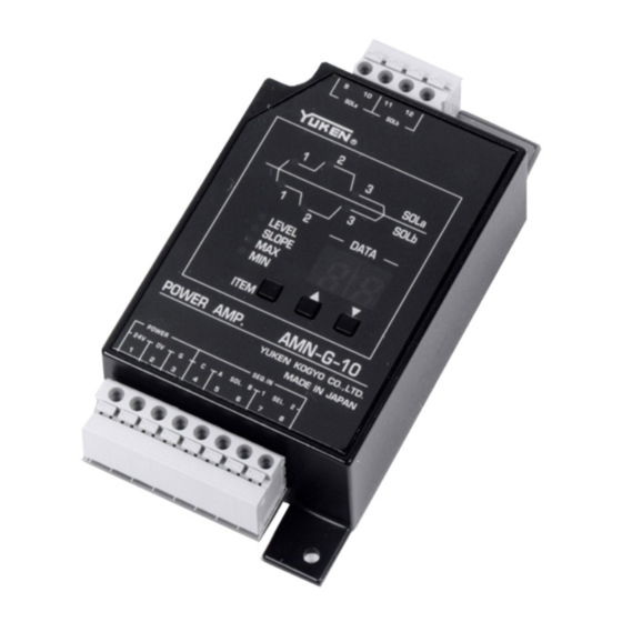
Page 8: External Dimensions And Location Of Control Buttons
1.3 External Dimensions and Location of Control Buttons Terminal block (solenoid output) Point display Data display Item display Data setting buttons Terminal block (Power supply, sequence input) - 8 -... -
Page 9: Power Amplifier Cabling
2. Power Amplifier Cabling WARNING Always disconnect the main power supply before installing, moving or connecting cables to the power amplifier. Failure to do so may result in electric shock or fire, or misoperation or damage to the amplifier. Always use the specified power supply voltage for this product. Using an incorrect power supply may cause fire or electric shock. -
Page 10: Cabling Precautions
2.2 Cabling Precautions 2.2.1 Connecting Cables to the Screwless Terminal Block Range of cables that can be used: φ φ Single-core 0.4 (AWG26) to 1.2 (AWG16) φ Twisted-core 0.3 mm (AWG22) to 1.25 mm (AWG16) Wire diameter 0.8 or more Standard length of wire to strip: 11 mm Points to note when connecting wires... -
Page 11: Setup
3. Setup WARNING Always turn on the power to the power amplifier before turning on the power to hydraulic equipment and machinery. Failure to turn the power on in this sequence may cause the equipment to misoperate. 3.1 Functions of Each Button 1) ITEM change key (Switches between monitor, data set, and control parameter set modes) Used to change the display mode and select the setting item. -
Page 12: Mode Settings
3.2 Mode Settings Pressing the ITEM key for 3 seconds or more in monitor mode changes to control parameter setting mode. Use the ITEM + [ ] and [ ] keys to select the item and use the [ ] and [ ] keys to change the contents of the selected item. - Page 13 6) Slope waveform selection If you wish to avoid any shock to the device on which you are performing hydraulic control, selecting an S shaped curve for the slope waveform smoothes any shock when movement starts or stops. Setting: 0 to 9 (10 types) (Preset in factory: Type 0) Slope waveform types The figures in brackets ( ) indicate the points at which the waveform curves.
- Page 14 7) Current limit setting Sets the current limit value. Setting range: 0.0 to 2.0 [A] (Preset in factory: 1.1 [A]) Set 1.1 [A] if driving the EDFG valve. (See section 4.2) 8) Dither frequency setting Sets the dither frequency. Setting range: 0 to 9 (100 to 190 [Hz]) (Preset in factory: 2 (120 [Hz])) Dither frequency = (Dither setting) ×...
- Page 15 12) Control mode selection Selects the control mode. P.0 : Shockless control mode (Preset in factory) P.1 : G valve control mode 1) Shockless control mode: This mode outputs a L→H→L shockless pattern. Output Input Signal 2) G valve control mode: This control mode is equivalent to that for shifting time adjustable type shockless valve.
-
Page 16: Output Data Settings
3.3 Output Data Settings 1) Data setting procedure Press the ITEM key twice in succession to select data set mode. (The mode changes alternately at each key press) ITEM Use the ITEM + [ ] and [ ] keys to select the item or point to set. ▲... - Page 17 3) Slope time setting The following describes the procedure for setting the slope time in switching the current output to the next output. When slope constant selected: SLOPE = [MAX slope time]×[SLOPE setting]×([Target LEVEL] – [Current LEVEL]) When time constant selected: SLOPE = [MAX slope time]×[SLOPE setting] Slope setting display When setting the slope, the SLOPE and corresponding point indicating lamps turn on.
-
Page 18: Operation
4. Operation 4.1 Sequence Input Signals 1) Shockless control mode The input to the power amplifier is a special 4-bit code input from the terminal block (terminals 5 to 8). Input Signal vs. Output SOLa SOLb SEL1 SEL2 Output Terminal 5 Terminal 6 Terminal 7 Terminal 8... -
Page 19: Control Flow Rate And Settings
4.2 Control Flow Rate and Settings 1) Shockless type proportional directional and flow control valve Model : EDFG-01-30-3C2-XY-50 2) Current-flow characteristics and settings Valve differential pressure: 7MPa SOLa energized SOLb energized PBAT flow PABT flow Flow [l/MIN] Output Current [A] Current limit Current limit Level setting... -
Page 20: Storage Of The Power Amplifier
If you have any requests relating to YUKEN products or require service, contact the dealer from whom you purchased the product, your local YUKEN sales representative, or the department listed below. YUKEN KOGYO CO., LTD. International Business Department (Tokyo office): Hamamatsucho Seiwa Bldg., 4-8, Shiba-Daimon...
Need help?
Do you have a question about the AMN-G-10 and is the answer not in the manual?
Questions and answers