
Summary of Contents for SEEIT TL866II+
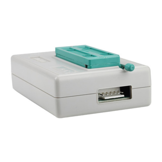
- Page 1 TL866II+ Universal Programmer with ZIF40 socket and SPI connector EPROMs / EEPROMs / I2C EEPROMs / FLASHs / SPI FLASHs / Microcontrollers / Logic IC test User manual (v1.20)
- Page 2 SEEIT is a registered trademark. SEEIT can be held responsible for no account for damages of whatever nature being able to result from the use of programmer. All rights reserved. Any reproduction, complete or partial, whatever process it is, of the software, the time switch or the documentation is illicit, (law n°92-597 of 1...
- Page 3 Performance of this programmer: Well-designed cheap professional programmer, Production of high-density SMD technology, a unified user interface, easy to use, fully functional, reliable program running of application software, ultra-small code -runs faster, supports bilingual(English and Chinese), it can automatically identify the operating system to install and run under WIN 2000/WIN XP/VISTA/WIN78/10 (32BIit/64Bit).
- Page 4 whether the code is used by other chips. Through custom encryption algorithm, it can stop those who decrypt chips with ulterior motives from directly using. The encryption algorithm is so complex that it is not easy to decrypt. But, about "encryption", there is a problem for developers - each chip is different - it is impossible to manually calculate one by one and respectively compile source code if the algorithm is complex.
- Page 5 Quick start guide: I/ Be ready for the hardware: Please make sure properly installed the application software and USB driver of the universal programmer before connecting the USB communication line. At this time, the red power supply indicator shows proper connection (lights up) and the yellow power supply indicator goes out waiting for programming.
- Page 6 IV/ Set chip configuration information and lock option: Please press “CONFIG” button in the Buffer select if you need to protect the chip or do other config operations. And then bring out the config dialogue box. The config information is different from the chip model. For example, if you select as AT89S8253, the below dialogue box will be brought out: Do the next one after setting up the configuration information and protection option V/ programming set:...
- Page 7 File menu : File menu items are as follows: ◆ Open file Load the hexadecimal file or binary file to the specified buffer, GAL chip should be loaded JED format file. ◆ Save file Save the present buffer as the HEX file of hexadecimal format or BIN file of binary format. Save as JED format file when programming GAD chip.
- Page 8 Project menu: In order to make the chip programming process more reliable, the project file needs to be set up. This file has the current buffer data and working environment settings, including the current device information, all Options settings and related settings of automatic numbering.
- Page 9 Modify password: Re-set the project password Prompt: An exact description of the project can distinguish from a large number of projects. The project mode is suitable for mass production. The project file has been encrypted. Proper protection of the project password can stop from copying. It can protect data to some extent.
- Page 10 Calculator: This is a calculator that comes with Windows and the scientific model calculation is very convenient for a variety of formats. Programmer Self-Check: Self-test on the programmer hardware Click to pop up the following dialog box: Note: Please remove the IC in the 40-PIN socket and ICSP cable before programmer begins to self-check. The IC may be damaged if no removing.
- Page 11 Help menu: Help menu items are as follows: Help: Shortcut keys F1 or click <help> to pop up the help files About TL866II+ : The programmer information is shown below: As shown above, "DEV Code" and "Serial" are the unique number of each programmer and this encrypted serial number is randomly generated 24 digits within the programmer hardware.
- Page 12 How to edit the Buffer: Define Block: Define block in two ways. 1. The first method: press the mouse left key and move the mouse to select a block of buffer data, right click to pop up the dialog box as shown below: 2.
- Page 13 Paste: Function: fill the buffer with the copied block Operation: move the cursor to allow the buffer to the start address and press <CTRL + V> shortcut key to complete the paste. A region data is copied to B region as below: Note: In order to speed up the paste, the clipboard data format is binary format this programmer exclusively uses, so other WINDOW applications can not directly use the copied data in the clipboard.
- Page 14 How to program a component: I/ Select IC: Directly select the chip you want to program according to the IC type that is easy and convenient to operate. Note: For the IC with same model but different package, if all of the packages (no including DIP package) cannot be listed, you can directly connect the corresponding pins to program by referring to the IC product manual.
- Page 15 3. Click [Write] Button in the toolbar to pop up the following dialog box: Firstly set [Program Range], including [CODE] [DATA] [FUSE] [LOCK]. Press [Program] button to start programming the chip. Tips: After programming, the programming time for each buffer is shown in the information column. Most of the chips will be automatically checked in the process of programming and the program operation will be immediately terminated if there is an error.
- Page 16 VI/ Device\Verify: Click [Verify] Button in the toolbar to pop up the following dialog box: By default, chip ID will be checked before erase. You can select the region you want to verify and the default is the entire region. Click [Verify] button in the dialog box to start.
- Page 17 The value of IC config information in the lower right is corresponding to config interface: Click Config interface and the value of the config information will be automatically changed. 1. Different chip has different configuration information, so firstly users should check the IC datasheets in order to properly configure the chip.
- Page 18 Firstly select the Auto Inc. mode. There are four algorithm modes to choose from the dialog box and the detailed instructions are as below: 1. The default increment algorithm <Default INC.> This algorithm interface is shown above, a set length of number is placed in the start address and the number will be increased according to the <Inc.
- Page 19 After making DLL file, you copy them to the application subdirectory : \Serialnumber, that's OK. You can select your algorithm file in the <user algorithm> list. The following operating steps are the same as other algorithms. Important note: 1. After setting the above, the programmer will not automatically add the serial number you set to the chip when programming, unless you tick off <Auto Serials No.>...
- Page 20 Click [View ICSP Connection] button to pop up the in-circuit serial programming wiring diagram, as shown below: (Different chip has different ICP connection method) Note: 1. Now ICSP can in-circuit serial program ATMEL89S51, ATMEL89S52, AT45DBxxx, a whole series of AVR ATMEGAxxx, MICROCHIP PIC10Fxxx 12Fxxx 16Fxxx 18Fxxx, as well as a full serial of SYNCMOS SM59Dxx SM59Rxx.
Need help?
Do you have a question about the TL866II+ and is the answer not in the manual?
Questions and answers