Advertisement
Quick Links
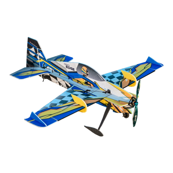
TA HORIZONS 33'' MIGHTY EDGE
ASSEMBLY INSTRUCTION MANUAL
Technical Data-
Wingspan : 33"
Length
AUW : 180-220g
(Depends upon the setup used)
Setup Recommendations (Not Included)-
Motor : 18-22G 1800-2300KV Outrunner
ESC
: 35"
Servos
Propeller : 8-9" electric
Battery
(T-Motor AS2304 1800KV Recommended for Super Light Setup)
: 12-16 amp
: 3Pcs 9gms each
: 450-600Mah 2-3S Lipo
Page 1
Advertisement

Related Manuals for TA HORIZONS MIGHTY EDGE 33


Summary of Contents for TA HORIZONS MIGHTY EDGE 33
- Page 1 TA HORIZONS 33’’ MIGHTY EDGE ASSEMBLY INSTRUCTION MANUAL Technical Data- Setup Recommendations (Not Included)- Motor : 18-22G 1800-2300KV Outrunner Wingspan : 33" (T-Motor AS2304 1800KV Recommended for Super Light Setup) : 12-16 amp Length : 35” Servos : 3Pcs 9gms each Propeller : 8-9”...
- Page 2 These instructions are suggestions only on how to assemble this model. There are other ways & methods also to do so. TA Horizons has no control over the final assembly because it specifically depends upon the knowledge and experience of the person involved directly in its handling, or the manner in which the model is assembled, radio gear installed, and electronic parts are used and maintained.
-
Page 3: Kit Contents
150mm L X 2 pictured items. If any of the airframe or hardware RUD 420mm L X 1 ELE 380mm L X 1 items are missing, contact TA Horizons before AIL 100mm L X 2 starting your build. Undercarriage sq.tube... - Page 4 TOOLS AND BUILDING MATERIAL REQUIRED • Needle Nose Pliers • Heat Gun • Wire Cutters • Tape Measure and Ruler • Low Temp Hot Glue Gun • Black Sewing Thread • Scissors • High Viscosity CA • Small Phillips Screw Driver •...
- Page 5 The Build Please Note: Few pictures shown below are of different plane and for reference purpose only. (This is mandatory step)locate the hinged items as shown above, 2. Locate the 5mm X 675mm CF Spar shown in the picture above. Bend them back on to each other as shown and let set for at least 2 hours.
- Page 6 The Build Please Note: Few pictures shown below are of different plane and for reference purpose only. 5X1X325mm GEL GLUE (HV) 7. Locate the 1X5mm 325mm L stripe, Glue it in the pre-cut groove. 8. Apply a thin layer on gluing surface. Use a spray activator (Kicker) to cure, wipe off the excess glue if needed.
- Page 7 The Build Please Note: Few pictures shown below are of different plane and for reference purpose only. REGULAR THIN CYNO ONLY 3X0.5X170MM 13.Locate the 3X0.5mm 170mm stripe for tail re-inforcement, insert 14. Use thin cyno to glue this stripe, use spray activator to cure it. the stripe vertically into the precut slot, make sure it is completely inserted into the slot.
- Page 8 The Build Please Note: Few pictures shown below are of different plane and for reference purpose only. 19.Time to do Aileron trussing. 20. Use the yellow marked part of foam as aileron truss support. 200MM RODS 150MM ROD 21. Locate the triangular joiner that will be placed on the underside of 22.
- Page 9 The Build Please Note: Few pictures shown below are of different plane and for reference purpose only. ACTIVATOR GEL GLUE (HV) 25.Apply a thin layer of HV CA to the mating surfaces of the lower 26. Bring the two pieces together. You will have a little time to work with vertical fuselage.
- Page 10 The Build Please Note: Few pictures shown below are of different plane and for reference purpose only. 31. Optionally use a heat shrink tubing for better cosmetic finish. 32. Glue the shown parts over the pre cut slots, for landing gear assembly.
- Page 11 The Build Please Note: Few pictures shown below are of different plane and for reference purpose only. GLUE HERE 37. Make sure the lower part of fuselage is straight while installing the 38. Install the wheel over the shaft, make sure it is spinning gears using the building jig.
- Page 12 The Build Please Note: Few pictures shown below are of different plane and for reference purpose only. 100mm ROD 150mm RODS Locate and glue the half part of SFG works as wing truss support, 44. Rods bracing the lower part of fuselage are 150mm X 12 and glue it in pre-cut slot like shown in the picture.
- Page 13 The Build Please Note: Few pictures shown below are of different plane and for reference purpose only. AILERONS RUDDER ELEVATOR REGULAR THIN CYNO ONLY 49. Locate the servo trays and control horns, for elevator control horn 50. Locate the servo arm extenders install the extenders over the stock you will notice a small square shaped cutout on the underside.
- Page 14 The Build Please Note: Few pictures shown below are of different plane and for reference purpose only. 55. Time to install the servos, put the aileron servo in place and glue it. 56. Glue the elevator servo in a direction in which the arm hub matches the center line of pre cut elevator arm slot.
- Page 15 The Build Please Note: Few pictures shown below are of different plane and for reference purpose only. THIN CYNO 61. Cut the rod at the position shown in the above image to fit in the 62. Above is the finished linkage setup with aileron centered and rod quick link.
- Page 16 The Build Please Note: Few pictures shown below are of different plane and for reference purpose only. 67. Use the assembly jig to center the elevator. 68. With the jig in place, Cut the rod at the position shown in the above image to fit in the quick link.
- Page 17 The Build Please Note: Few pictures shown below are of different plane and for reference purpose only. GEL GLUE (HV) 73. Once the aileron and elevator linkages are set up, use the same 74. Go Slow, once again it is so important to keep this as straight as process as gluing the bottom of the fuse to glue the top of the fuselage possible.
- Page 18 The Build Please Note: Few pictures shown below are of different plane and for reference purpose only. 200MM RODS . Above is the finished linkage setup with rudder centered and rod 80. Shown above is the 200mm X 2 carbon rod that will go on each well fitted and glued in both the quick links with all the guides in place.
- Page 19 The Build Please Note: Few pictures shown below are of different plane and for reference purpose only. OPTIONAL 85. Slide in and glue the upper half of SFG using HV CA to the precut 86. If desired, locate these smaller side force generators that will be slots like shown in the above image.
-
Page 20: Cg And Control Throws
CG and Control Throws CENTER OF GRAVITY CG 230mm Initial CG is located 230mm from the nose of the aircraft (Not from the motor) CONTROL THROWS In order to achieve the control throws as described for “Extreme & 3D”, it is imperative that the control surface, linkages, rod ends, etc, all move freely over the entire range, including... - Page 21 Thank You T hank You.. Thank you for your purchase at TA Horizons. We sincerely hope that our products can provide the same thrill to you that we experience in this hobby. The motive of this project is to spread the outcome of my love for teaching and share my knowledge and experience with every enthusiast out there.
Need help?
Do you have a question about the MIGHTY EDGE 33 and is the answer not in the manual?
Questions and answers