Table of Contents
Advertisement
Available languages
Available languages
Quick Links
Advertisement
Table of Contents

Summary of Contents for iAN QAD-90011
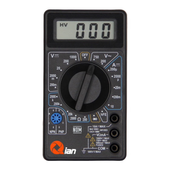
- Page 1 DIGITAL MULTIMETER MULTIMETRO DIGITAL MODEL: QAD-90011 Please read carefully before using your equipment and store this manual for future reference. Por favor léalo cuidadosamente antes de usar su equipo y guárdelo para uso de futuras consultas. USER MANUAL / MANUAL DE USUARIO...
-
Page 2: Warranty And Product Information
WARRANTY AND PRODUCT INFORMATION These terms shall be governed and construed under laws of the jurisdiction in which the product was purchased, if any term here is held to be invalid or unenforceable, such term (in so far as it is invalid or unenforceable) shall be given no effect and deemed to be excluded without invalidating any of the remaining terms. - Page 3 WARNING To avoid possible electric shock or personal injury, and to avoid possible damage to the Meter or to the equipment during testing, adhere to the following rules: Inspect the Meter’s case before using it, do not use the Meter if it is damaged or the case (or part of the case) is missing.
- Page 4 Do not use or store the Meter in an environment with high temperature, humidity, or near explosions, open flames or strong magnetic fields. The performance of the Meter may deteriorate after dampened. When using the test leads, keep your fingers behind the finger guards.
- Page 5 The Meter is suitable for indoor use. Turn the Meter power off when not in use and take the battery out and store when it won’t be used for a long time. Constantly check the battery for leakage when it has been used for a long time, and replace it if any leaking appears.
-
Page 6: General Specifications
GENERAL SPECIFICATIONS Max display: LCD 3 ½ digits (1999 count) 0.5” height Polarity: Automatic, indicated minus, assumed plus. Measure method: double integral A/D switch instrument Sampling speed: 2 times per second Over-load indication: “1” is displayed Operating Environment: 0°C~40°C, at <80%RH Storage Environment: -10°C~50°C, at <85%RH Power: 9V NEDA 1604 or 6F22 Low battery indicator: “... -
Page 7: Technical Specifications
TECHNICAL SPECIFICATIONS Guaranteed accuracy for 1 year, 23°C±5°C, less than 80%RH DC Voltage RANGE RESOLUTION ACCURACY 200mV 100uV ±(0.5% of rdg + 3D) 2000mV 10mV ±(0.8% of rdg + 5D) 200V 100mV 1000V ±(1.0% of rdg + 5D) OVERLOAD PROTECTION: 220V rms AC for 200mV range and 1000V DC or 750V rms for all ranges. - Page 8 DC CURRENT RANGE RESOLUTION ACCURACY 200uA 100nA 2000uA ±(1.8% of rdg +2D) 20mA 10uA 200mA 100uA ±(2.0% of rdg +2D) 10mA ±(2.0% of rdg +10D) OVERLOAD PROTECTION: 500mA 250V fuse (10A range unfused). MEASURING VOLTAGE DROP: 200mV RESISTANCE RANGE RESOLUTION ACCURACY 200Ω...
-
Page 9: Dc Current Measurement
MAXIMUM OPEN CIRCUIT VOLTAGE: 3.2V. OVERLOAD PROTECTION: 15 seconds maximum 220Vrms. OPERATING INSTRUCTIONS DC & AC VOLTAGE MEASUREMENT 1. Connect red test lead to “VΩmA” jack, Black lead to “COM” jack. 2. Set RANGE switch to desired VOLTAGE position, if the voltage to be measured is not known beforehand, set switch to the highest range and reduce it until a satisfactory reading is... -
Page 10: Resistance Measurement
3. Connect the test leads IN SERIES to the device or circuit being measured’s load. 4. Read current value on Digital Display. 5. Additionally, the 10A setting is designed for intermittent use only. Maximum contact time of the testing leads with the circuit is 15 seconds, with a minimum wait time of 15 minutes between tests. -
Page 11: Diode Measurement
DIODE MEASUREMENT 1. Red lead to “VΩmA”, Black lead to “COM”. 2. Set RANGE switch to “ ” position. 3. Connect the red test lead to the anode of the diode to be measured and black test lead to cathode. 4. -
Page 12: Battery And Fuse Replacement
BATTERY AND FUSE REPLACEMENT The fuses usually don’t need replacement and will only blow up as a result of an operation error. If “ ” indicator appears on the display, it means that the battery should be replaced. To replace battery & Fuse (500mA/250V) remove the 2 screws in the bottom of the case, then remove the old battery or Fuse and replace with new ones. - Page 13 GARANTÍA E INFORMACIÓN DEL PRODUCTO Estos términos se regirán e interpretarán de acuerdo con las leyes de la jurisdicción en la que se compró el producto, si alguno de los términos en este documento se considera inválido o inaplicable, dicho término (en la medida en que sea inválido o inaplicable) no tendrá...
- Page 14 ADVERTENCIA Para evitar posibles descargas eléctricas o lesiones a su persona, y para evitar posibles daños al multímetro o al equipo bajo prueba, cumpla con las siguientes normas: Antes de usar el multímetro, inspeccione la carcasa. No use el Medidor si está dañado o si se quitó la carcasa (o parte de la carcasa).
- Page 15 Utilice los terminales, la función y el rango adecuados para sus mediciones. No utilice ni almacene el medidor en un entorno de alta temperatura, humedad, ni cerca de explosivos, flamas o campos magnéticos fuertes. El rendimiento del multímetro puede deteriorarse después de humedecerlo. Cuando utilice los cables de prueba, mantenga los dedos detrás de los protectores de dedos.
- Page 16 Se debe usar un paño suave y un detergente suave para limpiar la superficie del multímetro durante el mantenimiento. No use abrasivos ni solventes, para evitar que la superficie del medidor sufra corrosión, daños y accidentes. El medidor es adecuado para uso en interiores. Apague el medidor cuando no esté...
-
Page 17: Especificaciones Generales
ESPECIFICACIONES GENERALES Pantalla: LCD de 3 ½ dígitos (cuenta de 1999) de 0,5” de altura Polaridad: Automática, negativa indicada, positiva implicita. Método de medición: instrumento de interruptor A/D integral doble Velocidad de muestreo: 2 veces por segundo Indicación de sobrecarga: se muestra “1” Entorno operativo: 0 °C~40 °C, a <80 % de HR Entorno de almacenamiento: -10 °C~50 °C, a <85 % de Potencia: 9V NEDA 1604 o 6F22... -
Page 18: Especificaciones Técnicas
ESPECIFICACIONES TÉCNICAS Precisión garantizada por 1 año, 23°C±5°C, menos del 80% de HR Voltaje CC RANGO RESOLUCIÓN PRECISIÓN 200mV 100uV ±(0.5% of rdg + 3D) 2000mV 10mV ±(0.8% of rdg + 5D) 200V 100mV 1000V ±(1.0% of rdg + 5D) PROTECCIÓN CONTRA SOBRECARGA: 220 V rms CA para el rango de 200 mV y 1000 V CC o 750 V rms para todos los rangos. - Page 19 RESPUESTA: Respuesta promedio, calibrada en rms de una onda sinusoidal. RANGO DE FRECUENCIA: 45Hz ~ 450Hz PROTECCIÓN CONTRA SOBRECARGA: 1000 V CC o 750 V rms para todos los rangos. CORRIENTE CC RANGO RESOLUCIÓN PRECISIÓN 200uA 100nA 2000uA ±(1.8% of rdg +2D) 20mA 10uA 200mA...
- Page 20 RESISTENCIA RANGO RESOLUCIÓN PRECISIÓN 200Ω 0.1Ω ±(1.0% of rdg +10D) 2000Ω 1Ω 20KΩ 10Ω ±(1.0% of rdg +4D) 200KΩ 100Ω 2000KΩ 1KΩ TENSIÓN MÁXIMA A CIRCUITO ABIERTO: 3,2V. PROTECCIÓN CONTRA SOBRECARGA: 15 segundos máximo 220Vrms. INSTRUCCIONES DE OPERACIÓN MEDICIÓN DE VOLTAJE CC Y CA 1.
-
Page 21: Medida De Corriente Cc
3. Conecte los cables de prueba al dispositivo o circuito a medir. 4. Encienda el dispositivo o circuito a medir, el valor del voltaje aparecerá en la pantalla digital junto con la polaridad del voltaje. MEDIDA DE CORRIENTE CC 1. Cable rojo a “VΩmA”. Cable negro a “COM” (para mediciones entre 200mA y 10A, conecte el cable rojo al conector “10A”... -
Page 22: Medida De Resistencia
MEDIDA DE RESISTENCIA 1. Cable rojo a “VΩmA”. Cable negro a “COM”. 2. Coloque el interruptor de RANGO en la posición de OHMIOS deseada. 3. Si la resistencia que se está midiendo está conectada a un circuito, apague y descargue todos los capacitores antes de la medición. - Page 23 MEDIDA DE TRANSISTOR HFE 1. Interruptor de RANGO a la posición hFE. 2. Determine si el transistor es PNP o tipo NPN y ubique los cables del emisor, la base y el colector. Inserte los cables en los orificios adecuados del enchufe hFE en el panel frontal.
Need help?
Do you have a question about the QAD-90011 and is the answer not in the manual?
Questions and answers