Advertisement
Quick Links
GB
30 100 600 - 4
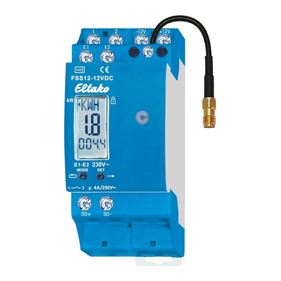
Wireless energy meter
transmitter module
FSS12-12V DC
Only skilled electricians may install this
electrical equipment otherwise there is
the risk of re or electric shock!
Temperature at mounting location:
-20°C up to +50°C.
Storage temperature: -25°C up to +70°C.
Relative humidity:
annual average value <75%.
Wireless energy meter transmitter module
for connecting to the SO interface of many
two-phase energy meter and three-phase
energy meter. Only 0.5 watt standby loss.
With load shedding relay 1 NO contact po-
tential free 4A/250V and with exchangeable
antenna. If required, a wireless antenna
FA250 or FAG55E- can be connected.
Modular device for DIN-EN 60715 TH35 rail
mounting.
2 modules = 36 mm wide, 58 mm deep
The energy meter transmitter module
FSS12 evaluates the signals of the S0 inter-
face of an electricity meter and sends
wireless telegrams with the consumption
and the meter reading to the Eltako wire-
less building for evaluation with the Pro-
fessional Smart Home Controller. On
three-phase energy meters, the data sent
includes normal rate (HT) or off-peak (NT)
energy tariff data, provided the E1/E2 ter-
minals on the three-phase energy meter
are connected to E1/E2 on the FSS12.
From production week 42/2012 also with
adjustable pulse rate.
2 modules wide switching power supply unit
SNT12-12V DC with 12W or 24W. If the relay
of the FSS12 is switched on, 0.6 watts are
required.
The setting and display screen is subdivided
into 3 elds:
Field 1:
The normal display is the unit of the meter
reading currently displayed in Field 3.
This alternates every 4 seconds with eit-
reading currently displayed in Field 3.
GB
5. LRN ashes and after con rming by pres-
This alternates every 4 seconds with eit-
sing MODE, a wireless teach-in telegram
her kilowatt hours kWh (KWH in display) or
is transmitted by pressing SET. If a smart
megawatt hours MWh (MWH in display).
30 100 600 - 4
metering display is already installed, it is
The display in Field 1 is supplemented by a
Wireless energy meter
used to teach-in the transmitter ID, provid-
+ sign after the reading to indicate that the
ed the receiver was set to LRN shortly
transmitter module
off-peak tariff rate is applied to E1/E2.
before. To transmit further wireless
Field 2:
FSS12-12V DC
teach-in telegrams, con rm the ashing
Instantaneous values of energy con-
LRN again by pressing MODE and transmit
sumption (active power) in watt (W) or
by pressing SET.
kilowatt (kW). The left-pointing arrow in
Only skilled electricians may install this
6. PSW ashes and after con rming by
Field 1 indicates an automatic switchover
electrical equipment otherwise there is
pressing MODE, press SET to set the pow-
from 0 to 99W to 0.1 to 65kW.
the risk of re or electric shock!
er threshold from 0 to 60kW for the load
Field 3:
shedding relay NO contact and a corres-
The meter reading is the normal display.
Temperature at mounting location:
ponding wireless telegram. The left poin-
Every 4 seconds the display alternates
-20°C up to +50°C.
ting arrow in Field 1 indicates kW. Con rm
between 3 whole numbers and 1 decimal
Storage temperature: -25°C up to +70°C.
by pressing MODE.
point (from 0.1 to 999.9kWh) and 1 or max
Relative humidity:
In the setting 0.0, the relay contact closes
3 whole numbers (from 0 to 999MWh). At
annual average value <75%.
after switching over from normal rate HT to
freely chosen pulse rates whose last digit
off-peak NT. At the same time, a wireless
Wireless energy meter transmitter module
is not 0, the meter reading is displayed
telegram EIN (ON) is transmitted. When the
for connecting to the SO interface of many
without decimal place in increments of
device is switched over from NT to HT, AUS
two-phase energy meter and three-phase
1 kWh.
(OFF) is transmitted and the relay contact
energy meter. Only 0.5 watt standby loss.
Press the left button MODE to access Sett-
opens.
With load shedding relay 1 NO contact po-
ing mode. Press the right button SET to
With any other value from 1 to 60, the load
tential free 4A/250V and with exchangeable
browse through the setting options, enter or
antenna. If required, a wireless antenna
shedding relay switches on when the set
edit settings as required and nally con rm
FA250 or FAG55E- can be connected.
threshold value is overshot and switches off
by pressing MODE.
when the set threshold value is undershot
Modular device for DIN-EN 60715 TH35 rail
1. HT ashes to indicate normal rate meter
at a hysteresis of 25%. At the same time, a
mounting.
reading. Con rm by pressing MODE again
wireless telegram EIN or AUS is transmitted.
2 modules = 36 mm wide, 58 mm deep
and MWH ashes. SET changes the meter
The energy meter transmitter module
reading from 0 to 999 in Field 3. Press SET
Lock settings: Press MODE and SET to-
FSS12 evaluates the signals of the S0 inter-
brie y to increment by 1; hold down to in-
gether brie y and lock the ashing LCK in
face of an electricity meter and sends
crement rapidly. Release and press again
Field 1 by pressing SET. To unlock, press
wireless telegrams with the consumption
to change direction. Con rm by pressing
MODE and SET together for 2 seconds and
and the meter reading to the Eltako wire-
con rm the ashing UNL in Field 1 by press-
MODE even if nothing was entered.
less building for evaluation with the Pro-
ing SET.
2. KWH ashes and SET changes the meter
fessional Smart Home Controller. On
reading from 0.1 to 999.9 in Field 3, as be-
Wireless telegrams: Maximum every 130
three-phase energy meters, the data sent
fore with MWH. Also con rm the correct
seconds a performance telegram will be
includes normal rate (HT) or off-peak (NT)
entry by pressing MODE.
sent and the display will be updated. Other-
energy tariff data, provided the E1/E2 ter-
3. NT ashes and the off-peak meter read-
wise a telegram will be sent within 20 se-
minals on the three-phase energy meter
ing may be displayed as described under
conds if the power changed by at least 10%.
are connected to E1/E2 on the FSS12.
HT above.
A switchover from HT to NT is transmitted
From production week 42/2012 also with
4. S0 ashes and after con rming with
immediately in the same way as a meter
adjustable pulse rate.
MODE, the number of S0 pulses (pulse
reading change. A full telegram comprising
2 modules wide switching power supply unit
rate) in box 3 of the energy meter are en-
meter reading HT, meter reading NT and po-
SNT12-12V DC with 12W or 24W. If the relay
tered per kWh. This will be provided by
wer is transmitted 20 seconds after the po-
of the FSS12 is switched on, 0.6 watts are
the energy meter imprint. 0010, 0100,
wer supply is switched on and then every
required.
0200, 0500, 0800, 1000 or 2000 are set-
10 minutes. The LED lights up brie y when a
The setting and display screen is subdivided
table with SET. If the MODE and SET keys
telegram is transmitted.
into 3 elds:
are pressed mutually, S0 + ashes on the
The power display in Field 2 depends on
Field 1:
display and the impulse rate can be
the number of S0 pulses per KWh from the
The normal display is the unit of the meter
chosen freely with SET. MODE con rms
meter and is updated every
reading currently displayed in Field 3.
the entry.
130 seconds.
This alternates every 4 seconds with eit-
meter and is updated every
130 seconds.
EEP A5-12-01:
5. LRN ashes and after con rming by pres-
The minimum load displayed is
ORG = 0x07
sing MODE, a wireless teach-in telegram
14 watts at 2000 pulses per kWh,
is transmitted by pressing SET. If a smart
Data_byte3 to Data_byte1 form a 24-bit
28 watts at 1000 pulses/kWh,
metering display is already installed, it is
binary coded number
35 watts at 800 pulses/kWh,
used to teach-in the transmitter ID, provid-
Data_byte3 = Data Byte 3 (MSB) 0...16777215
56 watts at 500 pulses/kWh,
ed the receiver was set to LRN shortly
Data_byte2 = Data Byte 2 0...16777215
140 watts at 200 pulses/kWh,
before. To transmit further wireless
Data_byte1 = Data Byte 1 (LSB) 0...16777215
280 watts at 100 pulses/kWh and
teach-in telegrams, con rm the ashing
2800 watts at 10 pulses/kWh.
Data_byte0 = DB0_Bit4 = tariff changeover
LRN again by pressing MODE and transmit
(0 = Normal rate, 1= Off-peak rate)
by pressing SET.
DB0_Bit3 = LRN Button (0 = teach-in
6. PSW ashes and after con rming by
Technical data
telegram, 1 = data telegram)
pressing MODE, press SET to set the pow-
Rated switching capacity
DB0_Bit2 = data content switchover:
er threshold from 0 to 60kW for the load
Incandescent lamp and
1 = momentary power in watts, 0 = meter
shedding relay NO contact and a corres-
halogen lamp load
230V
1)
status in 0.1 KW/h
ponding wireless telegram. The left poin-
ting arrow in Field 1 indicates kW. Con rm
DB0_Bit1 = 0 ( x)
Standby loss (active power)
by pressing MODE.
DB0_Bit0 = 1 ( x)
1)
Applies to lamps of max. 150W.
In the setting 0.0, the relay contact closes
Possible values in data telegram:
after switching over from normal rate HT to
DB0 = 0x09 -> meter status normal
Typical connection
off-peak NT. At the same time, a wireless
rate in 0.1 KW/h
telegram EIN (ON) is transmitted. When the
DB0 = 0x19 -> meter status off-peak
device is switched over from NT to HT, AUS
rate in 0.1 KW/h
(OFF) is transmitted and the relay contact
DB0 = 0x0C -> momentary power in W,
opens.
normal rate active
With any other value from 1 to 60, the load
DB0 = 0x1C -> momentary power in W,
shedding relay switches on when the set
off-peak rate active
threshold value is overshot and switches off
Teach-in telegram: 0x48080D80
when the set threshold value is undershot
(is sent once at every power-up)
at a hysteresis of 25%. At the same time, a
wireless telegram EIN or AUS is transmitted.
When an actuator is ready for
Lock settings: Press MODE and SET to-
!
teach-in (the LED ashes at a low
gether brie y and lock the ashing LCK in
rate), the very next incoming signal is
Field 1 by pressing SET. To unlock, press
taught-in. Therefore, make absolutely
MODE and SET together for 2 seconds and
sure that you do not activate any
con rm the ashing UNL in Field 1 by press-
other sensors during the teach-in
ing SET.
phase.
Wireless telegrams: Maximum every 130
seconds a performance telegram will be
Manuals and documents in further
sent and the display will be updated. Other-
languages
wise a telegram will be sent within 20 se-
conds if the power changed by at least 10%.
A switchover from HT to NT is transmitted
immediately in the same way as a meter
reading change. A full telegram comprising
meter reading HT, meter reading NT and po-
wer is transmitted 20 seconds after the po-
wer supply is switched on and then every
10 minutes. The LED lights up brie y when a
telegram is transmitted.
The power display in Field 2 depends on
http://eltako.com/redirect/FSS12-12V_DC
the number of S0 pulses per KWh from the
meter and is updated every
130 seconds.
The minimum load displayed is
E
O
D
b
D
D
D
D
(
D
t
4A/250 V AC
D
1000 W
1
s
D
0,5 W
D
P
D
r
D
r
D
n
D
o
T
(
M
l
h
Advertisement

Related Manuals for Eltako FSS12-12V DC

Summary of Contents for Eltako FSS12-12V DC
- Page 1 MODE and SET together for 2 seconds and sure that you do not activate any and the meter reading to the Eltako wire- con rm the ashing UNL in Field 1 by press- and the meter reading to the Eltako wire- con rm the ashing UNL in Field 1 by press- MODE even if nothing was entered.
- Page 2 Hereby, Eltako GmbH declares that the radio Field 1 by pressing SET. To unlock, press 3 whole numbers (from 0 to 999MWh). At equipment type FSS12-12V DC is in com- taught-in. Therefore, make absolutely to change direction. Con rm by pressing...
Need help?
Do you have a question about the FSS12-12V DC and is the answer not in the manual?
Questions and answers