Advertisement
Quick Links
BV90 fire protection valves
- BV92 series -
Meet the current requirements and standards
■ Maintenance-free: Due to complete enclosure of the operation
unit and the release element, no function-preserving cleaning
or recurring lubrication and adjustment is necessary
■ Functional test: By simply opening and closing on site
Series BV92
NEW
with hygiene certificate
User Manual 5.51 (2021-07) 1
Advertisement

Summary of Contents for Wildeboer BV92 Series
- Page 1 with hygiene certificate BV90 fire protection valves - BV92 series - Meet the current requirements and standards ■ Maintenance-free: Due to complete enclosure of the operation unit and the release element, no function-preserving cleaning or recurring lubrication and adjustment is necessary ■ Functional test: By simply opening and closing on site Series BV92 User Manual 5.51 (2021-07) 1...
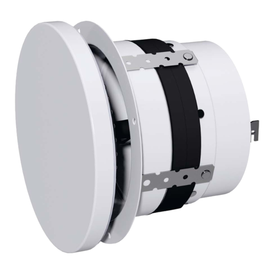
- Page 2 BV90 fire protection valves Function, volume flow setting Construction and function - The fire protection valve is essentially made up of an inte- grated duct for installation in walls or ceilings (1). - The valve disc (3) is inserted in it. - In the event of fire the release element (4) reacts and closes the valve disc with springs (3). The interlocks (5) are released by unscrewing them. In the pro- cess the inner locking pins are released. Left turn Left turn ⇒ see operating instructions Removing the valve disc (3) Inserting the valve disc (3) Setting the volume flow • In the factory the stroke marks , i.e. the lowest volume flows, are preset. ⇒ Nomograms, page 5 or 6 • Other settings to the stroke marks can be made on site: Stroke marks - To do so, remove the valve disc (3) from the integrated duct (1) by turning it to the left.
- Page 3 BV90 fire protection valves Description BV90 fire protection valves as per DIN EN 15650 New series BV92 Fire classifications: EI 30/60/90 (ve - ho, i ↔ o) S Fire resistance period: 30, 60 and 90 minutes Declaration of performance: DoP no.: CPR/BV90/002 Construction material certification non-combustible: Certificate MPA-BS 6000/593/18 Installation in suspended ceilings: General type approval Z-41.8-697 Steel fire protection valve. Shade: pure white RAL 9010. Installation housing with volume flow adjustable valve disc. A large free cross section makes for low pressure losses and low noise level.
- Page 4 BV90 fire protection valves Product and installation details Ø Da Ø D1 1 Integrated duct 2 Wall anchor on integrated duct 3 Thermally insulated valve disc 4 Release element with fusible link cap for 70 °C 5 Interlock for closed valve position Ø DN + 62 6 Setting sleeve for volume flow Example: 7 Lock nut Dry installation suspended in rigid ceilings 8 Spacer for release Holes ∅ D1 ⇒ Pages 8 to 13 9 Electrical limit switch 1 0 Connecting piece for ventilation duct 1 1 Screws min. 4 x 45 mm.
- Page 5 BV90 fire protection valves Dimensioning: Supply air underneath ceilings [m] Horizontal air stream path [m] Vertical air stream path [m/s] Flow velocity at point X,Y [m/s] Max. flow velocity downstream of air stream path X [m³/h] Volume flow Maximum flow velocity Example Specified: Volume flow V = 120 m³/h Air stream path X = Air stream path Y = 0 .125 m Result: M ax. flow velocity from diagram = 0 .18 m/s Calculate air stream path ratio X / Y = 2 / 0.125 = 16 Velocity ratio from diagram v / v = 0 .82...
- Page 6 BV90 fire protection valves Dimensioning: Pressure drop, sound power level with supply air Volume flow with fully opened fire protection valve [m³/h] Volume flow Valve position: [Pa] Total pressure drop [dB(A)] A-rated sound power level Example Size DN 200, valve position 2 Volume flow V = 171 m³/h Sound power level = 35 dB(A) Pressure drop = 36 Pa Supply air ∆p 30 40 50 70 100 150 200 300 400 600 1000 Volume flow...
- Page 7 BV90 fire protection valves Dimensioning: Pressure drop, sound power level with exhaust air Volume flow with fully opened fire protection valve [m³/h] Volume flow Valve position: [Pa] Static pressure drop [dB(A)] A-rated sound power level Example Size DN 125, valve position 2 Volume flow = 168 m³/h Sound power level = 50 dB(A) Pressure drop = 95 Pa Exhaust air ∆p 30 40 50 70 100 150 200 300 400 600 1000 Volume flow...
- Page 8 BV90 fire protection valves Installation in rigid walls and ceilings Minimum thicknesses W, D [mm] for Rigid walls can be constructed as masonry or from wallboards. They installation of BV90 fire protection valves: can be manufactured from concrete, light-weight concrete, gypsum etc., and also be designed as fire walls, shaft walls, shafts, ducts etc. A minimum bulk density of 450 kg/m³ is required. Required fire resistance 30, 60, 90 duration in minutes Solid brick, perforated brick, hollow block and ever greater thickness- es, higher densities and multiple shells can also be used. ≥ 95 mm Rigid walls W Rigid ceilings are generally made of cast-in-place concrete or light- weight concrete. ≥ 100 mm Rigid ceilings D Installation gaps for wet installation must be fully sealed with mortar of group II or III according to DIN 1053 or mortar of classes M 2.5 The fire protection valves must be installed with to M 20 according to EN 998–2; or with appropriate fire protection spacing of ≥ 200 mm between the integrated mortar or gypsum mortar.
- Page 9 BV90 fire protection valves Installation in light shaft walls Minimum thicknesses W [mm] for in- The shaft walls must be made up of at least 2 x 20 mm DF gypsum stallation of BV90 fire protection valves: boards according to EN 520 or equivalents. Metal studs and mineral wool can be arranged on one side. Required Installation gaps for wet installation must be fully sealed with mortar fire resistance period 30, 60, 90 of group II or III according to DIN 1053 or mortar of classes M 2.5 in minutes to M 20 according to EN 998–2; or with appropriate fire protection mortar or gypsum mortar. Shaft walls made of ≥ 40 mm gypsum or equivalent The walls are to be filled in the area of the installation openings with boards slabs of wall-building material, size ≥ DN + 150 mm.
- Page 10 BV90 fire protection valves Installation in metal stud walls clad on both sides (1) Standard installation Minimum thicknesses W [mm] for the The metal stud walls must be made up of at least 2 x 12.5 mm DF installation of BV90 fire protection valves: gypsum boards according to EN 520 or equivalents. The walls may be without or with mineral wool filling. Required Installation gaps for wet installation must be fully sealed with mortar fire resistance period 30, 60, 90 of group II or III according to DIN 1053 or mortar of classes M 2.5 in minutes to M 20 according to EN 998–2; or with appropriate fire protection Metal stud walls with at mortar or gypsum mortar. ≥ 95 mm least 2-layer cladding on In the area of the installation openings, the walls are to be filled with...
- Page 11 BV90 fire protection valves Installation in metal stud walls clad on both sides (2) Installation with installation tube Minimum thicknesses W [mm] for the The metal stud walls must be made up of at least 2 x 12.5 mm DF installation of BV90 fire protection valves: gypsum boards according to EN 520 or equivalents. The walls may be without or with mineral wool filling. Required fire resistance The installation of the installation pipes requires precisely fitting 30, 60, 90 period in minutes boreholes ∅ D2. The mounting supports (1), mounting pipes (14) and cover plates (15) Metal stud walls with at 70 mm must be fastened with screws (11) or (16)! least 2 layer cladding on 110 mm both sides Installation openings DN [mm] • (Core) hole ∅ D2 [mm] The fire protection valves must be installed with spacing of ≥ 200 mm between the integrated...
- Page 12 BV90 fire protection valves Installation in suspended or self-supporting, independently fire-resistant suspended ceilings (1) Suspended ceilings made of screwed and trowelled slab building materials and slab ceilings as inlaid con- structions with fire resistance classes F30, F60 or F90 Building materials of the suspended ceilings can be, for example, calcium silicate (Promat), vermiculite (Miprotec), gypsum (Rigips, Knauf, etc.). The suspended ceilings must comply with a general building authority test certificate (AbP) or be designed in accordance with DIN 4102-4.
- Page 13 BV90 fire protection valves Installation in suspended or self-supporting, independently fire-resistant suspended ceilings (2) Metal ceilings and suspended ceilings made of other building materials with fire resistance classes F30, F60, F90. The suspended ceilings must comply with a general building inspection test certificate (AbP) or be CE-marked. Installation examples Installation openings The fire protection valves are shown here without valve discs. for DN [mm] • Borehole ∅ D1 [mm] 120 220 for dry installation Tolerance + 2 mm F30 metal ceilings Spans ≤ 3 m and D ≥ 58 mm • Borehole ∅ D2 [mm] 160 for dry installation with Tolerance + 2 mm DN + 75 installation pipe...
- Page 14 • Cleaning work required in ventilation systems for hy- when installed should be made of normally flammable giene reasons must be performed in an operation-de- building material (B2 according to DIN 4102-1) or of pendent manner, and also includes the fire protection Aluflex pipe. valve. Connect the limit switch (item 9) electrically • • An operating manual for the BV90 fire protection valve, series BV92, is available on the internet. Electrical wiring must be installed on site. ⇒ www.wildeboer.de Connection cable colour coding blue blue grey grey black black Limit switch is not actuated: Limit switch is actuated: → Fire protection valve open → Fire protection valve closed...
- Page 15 ..Pc. Size: DN ..Volume flow: ..m³/h Pressure drop: ..Sound power level: ..dB(A) Manufacturer: WILDEBOER Type: BV90(series BV92) Supply and install complete with fastenings and other accessories. deliver:... install:... Select texts not highlighted in bold as required! Series BV92 Subject to change User Manual 5.51 (2021-07) 15...
- Page 16 E-mail: info@utrecht.wildeboer.eu FRANKFURT Internet: www.wildeboer.de/nl Leipzig office Telephone: +49 34444 - 310 - 0 E-mail: info@leipzig.wildeboer.de STUTTGART Internet: www.wildeboer.de MUNICH Ulm office Telephone: +49 7392 - 9692 - 0 E-mail: info@ulm.wildeboer.de Internet: www.wildeboer.de MAKE USE OF OUR STRENGTHS! WILDEBOER BAUTEILE GMBH...
Need help?
Do you have a question about the BV92 Series and is the answer not in the manual?
Questions and answers