Advertisement
Quick Links
Commisioning
It is important that the system be fully tested after installation.
Technical Data
Supply Voltage
Average Quiescent Current @
Relay Base Alarm Current (Relay Operated)
Relay contact ratings
Max. contact current
Max. contact voltage
Available modes
Operating Temperature
Connections
Base Size
Weight
© Copyright Apollo Fire Detectors Limited 2005-2011
Apollo Fire Detectors Limited, 36 Brookside Road, Havant, Hants, PO9 1JR, UK
Tel +44 (0)23 9249 2412 Fax +44 (0)23 9249 2754
Email: techsales@apollo-fi re.co.uk Website: www.apollo-fi re.co.uk
www.acornfiresecurity.com
39214-265/Issue 3
9 to 15 V DC
12V<10μA
<20mA @ 12V
1A (resistive)
<50V AC & <75V DC
Non-Latching or
Latching
-20°C to +70°C
(Non-Condensing
or Icing)
NC,C,NO,+,+,
L1 IN & L1 OUT (-)
100mm Diameter
25mm Deep
100 grams
4
www.acornfiresecurity.com
Series 65 12V Relay Base
Installation Guide
General
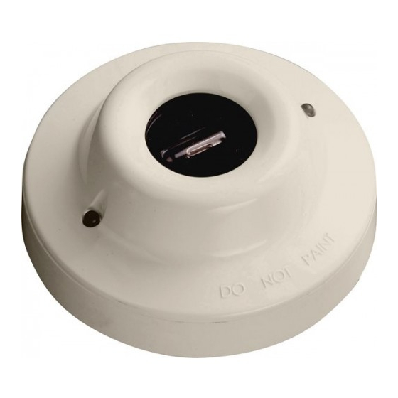
The Apollo Series 65 12V Relay Base part no. 45681-508 is a 12V relay base for use with Apollo
Series 65 smoke and heat detectors only. The base is designed to operate over a voltage
range of 9V to 15V DC.
The use of a 12V relay base means that standard (latching) smoke and heat detectors can be
used for both non-latching and latching applications, such as security control panels.
Latching/Non Latching
The relay can be confi gured as latching or non-latching by means of an internal jumper link.
If the jumper is in the right hand position (Fig.1,Position A) the relay base is in the non-latching
mode.
If the jumper is in the left hand position (Fig 1, Position B) the relay base is in the latching mode.
If the jumper is not fi tted, the base will default to non-latching.
Operating Principle
The relay base receives an alarm signal from the associated detector which latches.
In latching mode, the detector and relay remain latched until reset by removing the supply.
In the non-latching mode, when the associated detector has latched in alarm, the relay base
waits for approximately 15 seconds and then resets the detector by removing the supply auto-
matically. The detector will re-enter the alarm state if there is suffi cient smoke or heat present.
Mounting Instructions
1.
Secure the base to an even surface.
2.
Connect the wiring following the diagram overleaf.
3.
Ensure functional earth or screen continuity is maintained using the earth terminal on the
base if required.
4 . Fit the appropriate detector and lock it to the base using a hexagonal driver part no.
29600-095 if required.
1
Advertisement

Summary of Contents for Apollo 65 Series
- Page 1 (Non-Condensing General or Icing) The Apollo Series 65 12V Relay Base part no. 45681-508 is a 12V relay base for use with Apollo Connections NC,C,NO,+,+, Series 65 smoke and heat detectors only. The base is designed to operate over a voltage L1 IN &...
- Page 2 ------- ------- Position B (latching) L1OUT L1OUT EARTH EARTH © Apollo Fire Detectors Limited 2005/JDR Optional Fig 1 Latching and non-latching jumper positions (for monitored circuits - panel Terminal block connections Ancillary Note: Do not connect external wire to the -R terminal as this may prevent the relay base from...


Need help?
Do you have a question about the 65 Series and is the answer not in the manual?
Questions and answers