Advertisement
Introduction
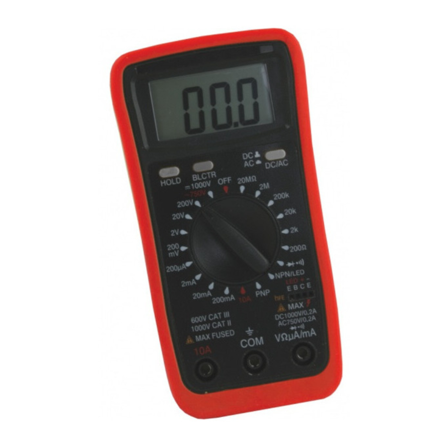
Digital tester for measurement of: AC/DC voltage, AC/DC current, resistance, diode test, transistor 2 LED test, continuity test.
It is designed for the professional at work in the field or laboratory and for in-door use.
| Code | Model | Description |
| VE772600 | VE 502E | Digital tester |
Description

- Backlit LCD Display
- Backlit Button
- Hold Button
- AC/DC Button
- Rotary Switch For Function Selection
- Socket For Test Transistor
- Jack VΩµA/mA
- Jack 10A
- Jack COM
GENERAL CHARACTERISTICS
- Maximum Indication: 1999 counts (3 1/2 digits) with large LCD display.
- Accuracies are ± (% reading + No. of digits)
- Sampling rate: 2-3 times reading per second (approximate).
- Push-type Switch buttons respectively for Data Hold-on(HOLD), Back-lighting(BLCTR) and AC/ DC (Interchange.)
- Single 20 positions easy to use rotary switch for Ten Functions and Range selection.
- High sensitivity of 100µV.
- Impedance: 10MΩ on all DCV & ACV Ranges.
- Automatic over-range indication with the "1" displayed.
- Automatic low battery power (6.4V) indication with the battery symbol "LOBAT".
- Automatic polarity indication on DC ranges.
- Diode testing with 1mA fixed current.
- Transistor hFE Test With ib-10µA.
- Continuity Test by beeper sounding below 50 ohm.
- Maximum common mode voltage: 380V DC/AC rms.
- Environment for guaranteed accuracy: 23°C±5°C, less than 75% RH.
- Temperature Scope: Operating 0°C to 40°C, 32°F to 104°F. Max. RH 80% to 31°C decreasing linear to 50% RH at 40°C.
- Storage: -10°C to 50°C, 14°F to 122°F at < 80% relative humidity.
- Power Supply: One 6F22 9-volt battery or equivalent.
- Size & Weight: 74(W) x 145(D) x 40(D) mm and 240g (including battery).
- Accessories: Operating manual, 1 Set of test leads with 20AWG 1000V Class PVC Wire.
- This instrument complies with insulation category (over voltage category), CAT II 1000V, CAT III 600V.
- Pollution degree 2 in accordance with IEC-664
| Function | Test Leads connected | Overload Maximum |
| V/DC | V/OHM + COM | 1000V DC |
| V/AC | V/OHM + COM | 750V rms. AC |
| OHM | V/OHM + COM | 380V DC/AC Protected |
| A/DC, AC | A + COM | 0.5A 250V DC/AC |
| 10A/DC, AC | 10A + COM | 10A 250V DC/AC |
| Diode, Buzz | V/OHM + COM | 380V DC/AC Protected |
| hFE/LED | Special Transistor Sockets | 1000 |
OPERATIONS
SAFETY WARNINGS AND CAUTIONS
- Check the 9-volt battery by setting the range switch to any other range but Off. If the battery is weak a sign will appear on the display. If this does not appear on the display proceed as below. See MAINTENANCE if the battery has to be replaced.
- The mark or sign
![warning]() next to the test lead jacks warns that the input voltage or current should not exceed the indicated values. This is to prevent damage to the internal circuit.
next to the test lead jacks warns that the input voltage or current should not exceed the indicated values. This is to prevent damage to the internal circuit. - The function switch should be set to the range to be tested before operation.
- If the voltage or current range is not known beforehand set the RANGE switch to a high range and work down.
- When only the figure " 1" is displayed, over-range is being indicated, and the FUNCTION switch must be set to a higher range.
- Do not measure large current 10 amp lasting more than 15 seconds. This can cause damage to the instrument and or equipment being tested and or injury to the user.
![shock hazard]() To avoid electric shock, disconnect measuring terminals before removing back cover.
To avoid electric shock, disconnect measuring terminals before removing back cover.
 next to the test lead jacks warns that the input voltage or current should not exceed the indicated values. This is to prevent damage to the internal circuit.
 To avoid electric shock, disconnect measuring terminals before removing back cover.
DC Voltage Measurement
- Connect the BLACK test lead to the COM jack and the RED test lead to the VΩµA/mA jack.
- Make sure that the AC/DC switch Button is on DC position (UP).
- Set the FUNCTION switch to the V range to be used and connect the test leads across the source or load under measurement. The polarity of the RED lead connection will be indicated at the same as the voltage.
- Get the readings from the LCD.
Note: Do not apply more than 1000V at all ranges to the input. Indication is possible at higher voltages, but there is danger of damaging the internal circuit.
| Range | Accuracy | Resolution | Over load Protection |
| 200mV | ± (0.5% of rdg. +1 digit) | 100µV | DC 1000V AC 750V rms. |
| 2.000V | ± (1.0% of rdg. +2 digits) | 1mV | |
| 20.00V | 10mV | ||
| 200.0V | 100mV | ||
| 1000V | ± (1.5% of rdg. +2 digits) | 1V |
AC Voltage Measurement
- Connect the BLACK test lead to the COM jack and the RED test lead to the VΩµA/mA jack.
- Push down the AC/DC switch Button. Then all the ranges of voltage are AC type.
- Set the FUNCTION switch to the V range to be used and connect the test leads across the source or load under measurement.
- Get the readings from the LCD.
Note: Do not apply more than 300V at 200mV range and 750V rms. at other ranges to the input. Indication is possible at higher voltages, but there is danger of damaging the internal circuitry.
| Range | Accuracy | Resolution | Over load Protection |
| 200mV | ± (1.0% of rdg. +3 digit) | 100µV | DC 1000V AC 750V rms. |
| 2V | ± (1.5% of rdg. +3 digits) | 1mV | |
| 20V | 10mV | ||
| 200V | 100mV | ||
| 750V | ± ( 2.5% of rdg. +4 digits) | 1V |
Frequency Range: 40Hz to 1000Hz
DC Current Measurement
- Connect the BLACK test lead to the COM jack and the RED test lead to the VΩµA/mA jack for Current Maximum of 400mA (Note: The polarity of the RED test lead is "+"). For a maximum of 10A, move the red test lead to the 10A jack.
- Make sure that the AC/DC switch Button is on DC position(UP)
- Set the FUNCTION switch to the A range to be used and connect the test leads in series with the load under measurement.
- Get the readings from the LCD.
Note: A. The Maximum input current is 0.5A or 10A depending on the jack used.
Excessive current will blow the fuse that must be replaced. Another fuse 10A protects the 10A range. The fuse rating should be 0.5A or no more than 10A to prevent damage to the internal circuit. The Maximum terminal voltage drop is 200mV except for the 10A range.
| Range | Accuracy | Resolution |
| 200µA | ± (1.2% of rdg. +1 digit) | 100nA |
| 2mA | 1µA | |
| 20mA | 10µA | |
| 200mA | 100µA | |
| 10A | ± (2.0% of rdg. +3 digits) | 10mA |
Overload Protection: Diode & 0.5A/250V Fuse of ordinary glass tube type but 10A range with 10A/250V fuse of ordinary glass tube type.
AC Current Measurement
- Connect the BLACK test lead to the COM jack and the RED test lead to the VΩµA/mA jack for a maximum of 0.2A. For a maximum of 10A, Move the RED test lead to the 10A jack.
- Push down the AC/DC switch Button. Then all the ranges of current are AC type.
- Set the FUNCTION switch to the A range to be used and connect the test lead in series with the load under measurement.
- Get the readings from the LCD.
Note: A. The Maximum input current is 0.2A or 10A depending upon the jack used. Excessive current can blow the fuse. Another fuse 10A protects the 10A Range. The fuse rating should be 0.5A or no more than 10A to prevent damage to the internal circuit. The maximum terminal voltage drop is 200mV except for the 10A range.
| Range | Accuracy | Resolution |
| 200µA | ± (1.5% of rdg. +3 digit) | 100nA |
| 2mA | 1µA | |
| 20mA | 10µA | |
| 200mA | 100µA | |
| 10A | ± (2.5% of rdg. +5 digits) | 10mA |
Overload Protection: Diode & 0.5A/250V Fuse of ordinary glass tube type, but 10A range with 10A/250V fuse of ordinary glass tube type. Frequency Range: 40Hz to 1000Hz. Indication: Average (rms. of sine wave).
Resistance Measurement
- Connect the BLACK test lead to the COM j jack and the RED test lead to the VΩµA/ mA jack (Note: The polarity of the RED test lead is "+")
- Set the FUNCTION switch to the Ω range to be used and connect the test leads across the resistance under measurement.
- Get the readings from the LCD.
Note:- If the resistance value being measured exceeds the maximum value of the range selected, an over-range indication will be displayed ("1"), then select a higher range.
For resistance of approximate 1M ohm and above the Meter may take a few seconds to become stable. This is normal for high resistance readings. - When the input is not connected i.e. at open circuit the figure "1" will be displayed for the over-range condition.
- When checking in-circuit resistance, be sure the circuit under test has all power removed and that all capacitors are fully discharged.
- If the resistance value being measured exceeds the maximum value of the range selected, an over-range indication will be displayed ("1"), then select a higher range.
| Range | Accuracy | Resolution | Overload Protection by PTC |
| 200 ohm | ± (1.2% of rdg. +2 digit) | 0.1 ohm | MAX DC/AC 380V rms. |
| 2K ohm | ± (1.0% of rdg. +2 digits) | 1 ohm | |
| 20K ohm | 10 ohm | ||
| 200K ohm | 100 ohm | ||
| 2M ohm | 1K ohm | ||
| 20M ohm | ± (2.5% of rdg. +4 digits) | 10K ohm |
Overload Protection by PTC: Max. AC/DC 380V rms.
Diode Measurement
- Connect the BLACK test lead to the COM jack and the RED test lead to the VΩµA/mA jack. (Note: The polarity of the RED test lead is "+")
- Set the FUNCTION switch to the
![]() range and connect the test leads across the diode under measurement. Display shows the approximate forward working voltage of this
range and connect the test leads across the diode under measurement. Display shows the approximate forward working voltage of this ![]() . Overload protection by PTC against high Voltage across Max. DC/AC 380V rms. at this Diode range.
. Overload protection by PTC against high Voltage across Max. DC/AC 380V rms. at this Diode range.
 range and connect the test leads across the diode under measurement. Display shows the approximate forward working voltage of this
  . Overload protection by PTC against high Voltage across Max. DC/AC 380V rms. at this Diode range.
Continuity Test
- Connect the BLACK test lead to the COM jack and the RED test lead to the VΩµA/mA
- Set the FUNCTION switch to the
![]() D range and the LCD will show the approximate resistance of the circuit.
D range and the LCD will show the approximate resistance of the circuit. - Connect the test leads to two points of circuit. If the resistance is lower than approx. 50 ohm, the buzzer sounds. Overload protection by PTC against high Voltage across Max. DC/AC 380V rms. at this range.
Transistor hFE & LED Test
- Set the Range switch to the "NPN/LED" to measurement LED or NPN transistor, to NPN to measurement PNP transistor.
- Determine whether the transistor is NPN or PNP and locate the Emitter, Base and collector terminals. Insert the pins into the proper holes of the special socket on the front panel.
- The display will read the approximate hFE Value at the test condition Base Current 10µ. VCE 2.8V.
- Get the readings from the LCD.
- For LED test, firstly set the Range switch to the "NPN" range, and then directly insert the two poles of LED separately into the "E" & "C" jacks of the special hFE input sockets on the front panel. A normal LED will be bright.
Back Lighting Operation
- Set the Range switch to any range but OFF.
- Push the BLCTR button two seconds, and the LCD will be lit for easy reading
- After 10 seconds, the light will turn off.
MAINTENANCE
Replacement for Batteries and/or Fuse should only be done after the test leads have been disconnected and POWER OFF.
9-Volt Battery Replacement
Remove the screws from the back case of the meter, and lift off the rear case.
Remove the worn battery and replace with a new 9-volt 6F22 battery or equivalent.
Close the back case and tighten the screws.
Fuse Replacement
When current measurements are impossible, check if overload protection fuse blown.
There are two kinds of fuses. When the fuses need replacement, use only 0.5A/250V or 10A/250V fuses identical in physical size to the original.

CLEANING
To clean the device, use a damp cloth after having turned it off and removing the leads.
Do not use liquids, solvents or other products that can reduce the safety level of the device.
REFERENCE STANDARDS
Compliance with Community Directives: 2014/35/EU (LVD), 2014/30/EU (E.M.C.D.) is declared in reference to the harmonized Standards
- EN 61010-1
- EN 61010-031
- EN 61326-1, EN 61326-2-2

This symbol on the product and/or accompanying documents means that used electrical and electronic products should not be mixed with general household waste.
For proper treatment, recovery and recycling, please take this product to designated collection.

Documents / ResourcesDownload manual
Here you can download full pdf version of manual, it may contain additional safety instructions, warranty information, FCC rules, etc.
Advertisement

Need help?
Do you have a question about the VE 502E and is the answer not in the manual?
Questions and answers