Table of Contents
Advertisement
Quick Links
Advertisement
Table of Contents

Summary of Contents for Deif ASC 150 Solar
- Page 1 ASC 150 Solar Operator's manual...
-
Page 2: Table Of Contents
......................................1.2 About the operator's manual ....................................... 1.3 Warnings and safety ..........................................1.4 Legal information ............................................2. About ASC 150 Solar 2.1 About controller operation ........................................2.2 Typical application examples ......................................2.2.1 Single controller (without power management) ............................... 2.2.2 With power management ...................................... -
Page 3: Introduction
1. Introduction Symbols for hazard statements DANGER! This shows dangerous situations. If the guidelines are not followed, these situations will result in death, serious personal injury, and equipment damage or destruction. WARNING This shows potentially dangerous situations. If the guidelines are not followed, these situations could result in death, serious personal injury, and equipment damage or destruction. -
Page 4: Warnings And Safety
Legal information Third party equipment DEIF takes no responsibility for the installation or operation of any third party equipment, including the genset. Contact the genset company if you have any doubt about how to install or operate the genset. Warranty... -
Page 5: About Asc 150 Solar
About controller operation The ASC 150 Solar controller controls and protects a photovoltaic system (PVS) with up to 32 inverters. You can add the controller to an existing plant as a single controller setup, or use it with other DEIF controllers in a power/energy management system. - Page 6 AGC Genset ASC Storage Application for an ASC 150 Solar in a power management system with AGC Mains, AGC Genset and ASC Storage This is an example of a grid-tied application. The ASC Solar is in a power management system with an AGC Mains, an AGC Genset, and an ASC Storage.
-
Page 7: Display, Buttons And Leds
More information See the ASC 150 Solar data sheet for the variations on the grid-tied and off-grid arrangement. You can select the plant mode for the AGC Mains controller when you have a power management system. ASC Solar configuration Basic settings > Application type > Type... - Page 8 Name Function Confirm the selection on the screen. Back Go to the previous page. The controller automatically starts and stops (and connects and disconnects) the PV, and AUTO mode automatically controls the power. No operator actions are needed. Silence horn Turns off an alarm horn (if configured) and enters the Alarm menu.
-
Page 9: Operating The System
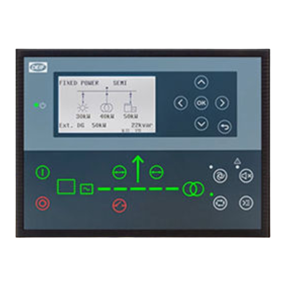
3. Operating the system Mimic function Settings > Basic settings > Controller settings > Display > LED mimic Parameter no. Item Range Standard 6082 LED mimic Guided Standard The control buttons and LEDs are shown. If you the stop the photovoltaic system (PVS), the PVS symbols are shown in red. -
Page 10: Display Settings
3. Modbus commands NOTE * The controller has a limited number of digital inputs. See Digital inputs in the ASC 150 Solar Designer's handbook for availability. Commands in SEMI-AUTO mode Command Description The start sequence for the photovoltaic system (PVS) is started. The breaker must be Start closed before you can start the system. -
Page 11: Utility Software
Utility software 3.5.1 Application supervision Use the application supervision function in the utility software to see the plant operation. This includes how much power each power source is producing. You can find Application supervision in the vertical menu in the utility software. 3.5.2 Data monitoring and counters Power meter monitoring... - Page 12 More information See General functions in the ASC 150 Solar Designer's handbook for more information about the functions in the utility software. OPERATOR'S MANUAL 4189341347A EN Page 12 of 32...
-
Page 13: Trending
3.5.3 Trending Use the trending function in the utility software to see real-time operation. Trending is possible when a PC is connected to the controller and the trending window is open. It is not possible for the controller to save the data. How to configure trending 1. -
Page 14: Modes Of Operation
4. Modes of operation Operate the ASC Solar controller in AUTO mode or SEMI-AUTO mode. In AUTO mode, the controller automatically starts and stops the PV, and controls the power automatically. In SEMI-AUTO mode, the operator or an external signal can open and close the PV breaker, and start the system. -
Page 15: Fixed Power
Fixed power In AUTO and SEMI-AUTO mode, the PV system (PVS) supplies the amount of power configured in the set point for fixed power. The controller does not need power measurements from other power sources in fixed power applications. ASC Solar Start sequence 1. -
Page 16: Mains Power Export (Mpe)
Mains power export (MPE) In this mode a constant level of power through the mains breaker is maintained. The power can be exported to the mains or imported from the mains, but always at a constant level. The set point can be 0 kW for zero export applications. Start sequence 1. - Page 17 Settings > Power set point > Mains power export and peak shaving > Day/night settings Parameter Text Range Default 7011 Daytime period, start hour 0 to 23 7012 Daytime period, start min. 0 to 59 7013 Daytime period, stop hour 0 to 23 7014 Daytime period, stop min.
-
Page 18: Peak Shaving
Peak shaving The PV system (PVS) supplies the extra load when the mains import increases to more than the maximum import set point. The system runs parallel to the mains. AUTO mode 1. Select AUTO mode. 2. The PV breaker closes automatically. 3. - Page 19 Settings > Power set point > MPE/peak shaving > Day/night settings Parameter Text Range Default 7011 Daytime period, start hour 0 to 23 7012 Daytime period, start min. 0 to 59 7013 Daytime period, stop hour 0 to 23 7014 Daytime period, stop min.
-
Page 20: Menus
5. Menus Menu structure The controller has two menu systems, which can be used without password entry: • The View menu system: Shows the operating status and values. The system has 20 configurable windows, that can be entered with the arrow buttons. •... -
Page 21: Menu Numbers
5.2.1 Menu numbers Each parameter has a menu number. You can find the number in the upper right corner on the display screen. You can also find the menu number with the utility software: 1. Select Parameters from the vertical toolbar on the left. 2. -
Page 22: View Menu
View menu The view menu is shown when the controller is turned on, and you can see the operating status and values. The event and alarms list will also be shown if an alarm is on. 1. Operating status 2. Values and information 3. -
Page 23: Display Views
Display text You can select five of the display texts for each display view. 5.3.2 Display views The controller has 20 display views, and 18 of the views are pre-configured. You can configure the views with the utility software. Line View 1 View 2 View 3... -
Page 24: Supervision Page
Line View 11 View 12 View 13 View 14 View 15 PV curtailed E, Angle BB-PV 0deg PVB status Energy Day 0kWh Energy Day 0kvarh week PV curtailed E, day Line View 16 View 17 View 18 View 19 View 20 Curtailment 0.0% PVB Operations 0 Multi Input 20 0... -
Page 25: Power Management System
You can select three different options for the bottom view line on the supervision page: • Option 1: Energy produced today (EDay) in kWh and the number of missing inverters (InvMis) • Option 2: Reactive power (PVQ) in kVAR and apparent power (PVS) in kVA •... - Page 26 Status text Condition BB V/Hz OK IN The voltage and frequency will be okay in ###s. BB VOLTAGE DETECTED Voltage detected on the busbar. BLACKOUT ENABLE Blackout close when there is a CAN failure. BLOCKED FOR CLOSING The breaker is unable to close. BLOCKED FOR START There are active alarms.
- Page 27 Status text Condition MAINS FAILURE TIMER Mains failure present timer. MAINS f OK DEL ####s Mains frequency is OK after a mains failure. The timer shown is the mains OK delay. MAINS P EXPORT AUTO The controller is in auto mode and ready to respond. MAINS P EXPORT SEMI The controller is in semi-auto mode and waiting for operator input.
-
Page 28: Service View
Status text Condition REM. FROM PMS PV Easy connect: Remove PV from PMS plant. REMOVE CAN CONNECTOR Remove the power management CAN lines. SELECT OPERATION MO An operation mode has not been selected. SELECT PLANT MODE A plant mode has not been selected. SETUP COMPLETED Successful update of the application in all the controllers. -
Page 29: Communication Troubleshooting
Use the shortcuts when the controller is in SEMI-AUTO mode. More information See General shortcuts in the ASC 150 Solar Designer's handbook for how to configure the general shortcuts. On the controller 1. From the view menu, push the Shortcut button to see the menu. - Page 30 2. Use the Up and Down buttons to go to General shortcuts , and push the button. 3. Use the Up and Down buttons to go to select a shortcut. OPERATOR'S MANUAL 4189341347A EN Page 30 of 32...
-
Page 31: Alarm Handling And Log List
6. Alarm handling and log list Alarm handling If the function Alarm Jump is on, the controller will automatically show the alarm list on the display screen when an alarm occurs. Service View > Display > Alarm Jump Parameter Text Range Default 9157... -
Page 32: Logs Menu
CAUTION Caution If an alarm is blocking the photovoltaic system (PVS) in AUTO mode from starting, the PVS starts automatically if the condition that triggered the alarm has gone and the alarm has been acknowledged. Logs menu These are the log sub-menus: 1.
Need help?
Do you have a question about the ASC 150 Solar and is the answer not in the manual?
Questions and answers