
Summary of Contents for NKE GYROPILOT 2
- Page 1 GYROPILOT 2 computer product reference : 90-60-130 INSTALLATION GUIDE REV 2 Zi de Kerandré – Rue Gutemberg – 56700 – HENNEBONT – FRANCE www.nke-marine-electronics.com +33 297 365 685...
-
Page 2: Table Of Contents
SOMMAIRE PRESENTATION ......................3 INSTALLING THE HYDRAULIC UNIT ................5 2.1 P ..................5 REPARING THE RUDDER ARM 2.2 I ..............6 NSTALLATION OF THE HYDRAULIC LINEAR DRIVE 2.3 I ................8 NSTALLATION OF THE HYDRAULIC PUMP 2.4 I ..............8 NSTALLATION OF THE RUDDER ANGLE SENSOR INSTALLATION AND CONNECTING THE COMPUTER .......... -
Page 3: Presentation
1 PRESENTATION This installation guide gives you all information : To install the computer Gyropilot 2 To install rudder angle sensor To install de the hydraulic unit To get the optimal performances from your pilot and your boat. See the installation guide for fluxgate compass and multifonction Gyrographic. - Page 4 - 4 - Gyropilot_2_um_EN_7_30...
-
Page 5: Installing The Hydraulic Unit
2 INSTALLING THE HYDRAULIC UNIT Read this guide entirely before starting the installation . Read the installation manual the hydraulic linear drive manufacture. 2.1 Preparing the rudder arm If it is not possible to install the drive unit directly to the steering quadrant, then you will have to buy and install a rudder arm for your rudder shaft. -
Page 6: Installation Of The Hydraulic Linear Drive
2.2 Installation of the hydraulic linear drive WARNING: The force developed by a hydraulic linear drive is very strong and could result in serious damage if impropally installed. The linear drive and the hydraulic pump must be positioned on an horizontal plan. Make sure that the linear drive support is positioned in the way that the rudder arm or rudder sector is in the same horizontal plan as the linear drive axis. - Page 7 2.2.2 Hydraulic linear drive type 40 for outboard mounting You will find with the hydraulic linear drive, the manufacturer mounting instructions. Dimensions for installation hydraulic linear drive type 40 outboard 2.2.3 Installation procedure Put the rudder to the axis Unscrew half the way the tip at the end of the drive rod, and pull the rod half the way out such as the length between the axis of the linear support and the thrust axis is equal to the rod length Place the linear drive at 90°...
-
Page 8: Installation Of The Hydraulic Pump
2.3 Installation of the hydraulic pump Select a location where it is easy to access to the pump for maintaining : oil adjust, speed setting. Fix the pump with 4 screw and nuts 6mm, on an horizontal plan. Not allowed Correct mounting WARNING: Don’t forget before start up , remove the shipping cap on the top of the oil tank and replace it... - Page 9 2.4.2 Installation procedure 1. Present the threaded rod in front of the rudder shaft, measure the maximum distance where you can place the sensor, in function of the rod length. The sensor arm will have to be able to rotate by 70° in both ways. 2.
-
Page 10: Installation And Connecting The Computer
Precautions The gyrometer sensor, essential to have good performances with the pilot, is integrated in the computer Gyropilot 2. As this sensor is very sensible, the computer must be : Mounted on a vertical wall, It is screw with 4 screw 4mm and the cable outlet are to the bottom. -
Page 11: Rvp Computer Reversible Pump )
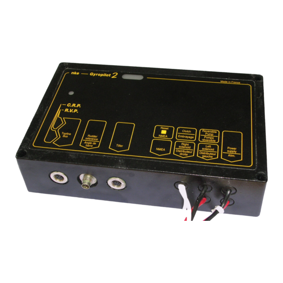
3.4 Electric diagram of Gyropilot 2 RVP computer (reversible pump) NMEA to BUS TOPLINE nke Gyrop lot 2 Calculateur Gyro2 Reversible Power Clutch Rudder pump supply Tiller reference fuse or circuit breaker white Linear drive power supply BLUE Topline Noir... - Page 12 GYROPILOT 2 RVP computer : bottom side Blue wire : ground Hydraulic pump Black wire: ground TOPLINE BUS Hydraulic power Rudder angle sensor supply Two white wire : clutch coil Tiller Red wire : Two white wires Brown wire :...
-
Page 13: Crp Computer
3.5 Electric diagram Gyropilot 2 CRP computer NMEA TOPLINE bus power Supply 12 Volts nke Gyrop lot 2 Calculateur Gyro2 Reversible Supply Clutch Rudder Pump Tiller reference Circuit breaker or fuse Linear drive power supply Black Topline cable Left solenoide... - Page 14 Right solenoide Power supply 3.5.1 GYROPILOT 2 CRP computer : bottom side The GYROPILOT 2 CRP computer is designed to drive the solenoids of an hydraulic system ; This hydraulic system is generally mounted on big boat. - 14 -...
-
Page 15: Connecting The Power Supply Of The Linear Drive Motor
3.6 Connecting the power supply of the linear drive motor ATTENTION: The Gyropilot 2 computer is designed to supply the linear power supply with 12VDC or 24VDC, but the TOPLINE bus must always be supplied with 12VDC. The supply power wires, from the computer and linear drive to the power battery, must be as short as possible. -
Page 16: Connecting The Computer To Topline Bus
If you reduce the length of the bus cable, strip and galvanise the wires before connecting them inside the terminal box. Gyropilote Graphic mode vent reel Page Consigne ang vent rl -30° -30° nke Gyrop lot 2 FLUXGATE COMPASS Angle de barre Calculateur Gyro2 Stop Auto Embrayage Pompe Alim. -
Page 17: Technical Specification
3.8 Technical specification Supply : 10 à 16VDC Consumption : 50mA, without the hydraulic linear unit. IP protection : IP67 Weight : 1kg, with cable Dimensions : width = 210mm ; height = 134mm ; thickness = 42mm Operating temperature : -10°C à +50°C Temperature of storage : -20°C à... -
Page 18: Initialisation Of The Computer
4 INITIALISATION OF THE COMPUTER This chapter describes the initialisation of the Gyropilot 2 computer and the Gyropilot Graphic. See also the Gyropilot Graphic user manual. 4.1 Initialisation After installing the Gyropilot, you must initialise the whole of your pilot system. This is... -
Page 19: First Start-Up Of The Pilot
4.2 First start-up of the pilot See the Gyropilot Graphic user manual. Note that powering up or powering down your installation is done using the auxiliary switch of the electric switchboard of your boat. Your installation must comprise two separate 12V power supplies : one for power to the hydraulic pump and to the computer and the other for the Gyropilot Graphic, the TOPLINE bus and the sensors. - Page 20 NOTES ________________________________________________________________________________________________ ________________________________________________________________________________________________ ________________________________________________________________________________________________ ________________________________________________________________________________________________ ________________________________________________________________________________________________ ________________________________________________________________________________________________ ________________________________________________________________________________________________ ________________________________________________________________________________________________ ________________________________________________________________________________________________ ________________________________________________________________________________________________ ________________________________________________________________________________________________ _______________________________________________________ - 20 - Gyropilot_2_um_EN_7_30...
- Page 21 NOTES ________________________________________________________________________________________________ ________________________________________________________________________________________________ ________________________________________________________________________________________________ ________________________________________________________________________________________________ ________________________________________________________________________________________________ ________________________________________________________________________________________________ ________________________________________________________________________________________________ ________________________________________________________________________________________________ ________________________________________________________________________________________________ ________________________________________________________________________________________________ ________________________________________________________________________________________________ _______________________________________________________ - 21 - Gyropilot_2_um_EN_7_30...
- Page 22 NOTES ________________________________________________________________________________________________ ________________________________________________________________________________________________ ________________________________________________________________________________________________ ________________________________________________________________________________________________ ________________________________________________________________________________________________ ________________________________________________________________________________________________ ________________________________________________________________________________________________ ________________________________________________________________________________________________ ________________________________________________________________________________________________ ________________________________________________________________________________________________ ________________________________________________________________________________________________ _______________________________________________________ - 22 - Gyropilot_2_um_EN_7_30...
Need help?
Do you have a question about the GYROPILOT 2 and is the answer not in the manual?
Questions and answers