Table of Contents
Advertisement
Quick Links
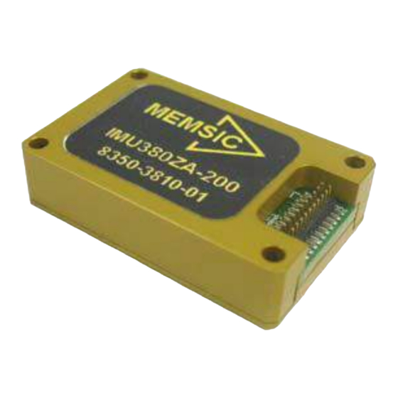
The MEMSIC IMU380ZA is a miniature fully-
calibrated inertial measurement system designed for
demanding embedded applications that require a
complete dynamic measurement solution in a robust
low-profile package. The IMU380ZA provides a
standard SPI bus for cost-effective board-to-board
communications.
Precision Farming
The MEMSIC IMU380ZA integrates highly-reliable MEMS
6DOF inertial sensors (optional 3-axis magnetic sensors) in
a miniature factory-calibrated module to provide consistent
performance through the extreme operating environments
in a wide variety of dynamic control and navigation
applications.
Applications
Precision
Farming
Platform
Stabilization
Unmanned Vehicle Control
Robotics
Control
Phone: 408.964.9700
Power Sensing Solutions for a Better Life
Antenna Stabilization
Fax: 408.854.7702
Document P/N: 6020-3810-03
IMU380ZA
INERTIAL MEASUREMENT SYSTEM
Features
Complete 6DOF Inertial
Optional 3-Axis
Standard and High Range
SPI (or UART) Interface
Update Rate, 1Hz to
1KHz Clock Synch
Miniature Package, 24 x 37 x 9.5 mm
Lightweight < 17 g
Low Power Consumption < 250 mW
Wide Temp Range, -40C to +85C
High Reliability, MTBF > 50k hours
E-mail: infoca@memsic.com
System
Magnetometer
Options
200Hz
Input
www.memsic.com
Advertisement
Table of Contents

Related Manuals for Memsic IMU380ZA


Summary of Contents for Memsic IMU380ZA
- Page 1 IMU380ZA Power Sensing Solutions for a Better Life INERTIAL MEASUREMENT SYSTEM The MEMSIC IMU380ZA is a miniature fully- calibrated inertial measurement system designed for demanding embedded applications that require a complete dynamic measurement solution in a robust low-profile package. The IMU380ZA provides a standard SPI bus for cost-effective board-to-board communications.
- Page 2 NAV-VIEW can also be used to set a Input Voltage (VDC) 3.0 to 5.5 wide range of user-configurable fields Power Consumption (mW) < 250 in the IMU380ZA to optimize the Digital Interface SPI or UART (user-configurable) system performance for highly Output Data Rate...
- Page 3 DMU380ZA Series USER MANUAL Document Part Number: 7430-3810-02 MEMSIC, Inc., 1759 McCarthy Blvd, Milpitas, CA 95035 Tel: 408-964-9700, Fax: 408-854-7702 email: infoca@memsic.com, website: www.memsic.com...
- Page 4 WARNING This product has been developed by MEMSIC exclusively for commercial applications. It has not been tested for, and MEMSIC makes no representation or warranty as to conformance with, any military specifications or that the product is appropriate for any military application or end-use.
-
Page 5: Table Of Contents
Reserved – Factory Use Only ................6 2.1.5 Mechanical Interface .....................6 Theory of Operation .....................7 DMU380ZA Series Default Coordinate System ..........11 3.1.1 Advanced Settings ..................12 IMU380ZA Theory of Operation................12 3.2.1 IMU380ZA Advanced Settings ..............13 3.2.2 IMU380ZA Built-In Test ................14 VG380ZA Theory of Operation ................14 3.3.1 VG380ZA Advanced Settings ..............16... - Page 6 DMU380ZA Series User’s Manual DMU380ZA Register Map .................32 DMU380ZA SPI Register Read Methodology ...........33 5.2.1 DMU380ZA SPI Port Polled-Mode Read ...........34 5.2.2 DMU380ZA SPI Port Burst-Mode Read .............35 Output Data Registers ..................37 System Registers ....................37 Diagnostic Status Register ..................38 DMU380ZA SPI Register Write Methodology ..........38 Configuration Registers ..................40 5.7.1 Self-Test/Data-Ready ..................40...
- Page 7 DMU380ZA Series User’s Manual 7.2.9 Error Response ....................54 Output Packets (Polled) ..................54 7.3.1 Identification Data Packet ................54 7.3.2 Version Data Packet ..................54 7.3.3 Test 0 (Detailed BIT and Status) Packet ............55 Output Packets (Polled or Continuous) ...............55 7.4.1 Scaled Sensor Data Packet 0 ...............55 7.4.2 Scaled Sensor Data Packet 1 (Default IMU Data) ........56 7.4.3...
- Page 8 DMU380ZA Series User’s Manual comSerialABIT Field ..................75 comSerialBBIT Field ..................75 softwareBIT Field ....................75 9.10 softwareAlgorithmBIT Field ................76 9.11 softwareDataBIT Field ..................76 9.12 hardwareStatus Field ..................76 9.13 comStatus Field ....................77 9.14 softwareStatus Field ..................77 9.15 sensorStatus Field ....................77 9.16 Configuring the Master Status.................77 9.16.1 hardwareStatusEnable Field ................78 9.16.2...
- Page 9 DMU380ZA Series User’s Manual Appendix B: NMEA Message Format ................93 GGA - GPS fix data .......................93 Appendix C: Sample Packet-Parser Code .................95 Overview........................95 Code listing ........................96 Appendix D: Sample Packet Decoding ................102 Doc# 7430-3810 Rev. 02 Page v...
- Page 10 DMU380ZA Series User’s Manual About this Manual The following annotations have been used to provide additional information. NOTE Note provides additional information about the topic. EXAMPLE Examples are given throughout the manual to help the reader understand the terminology. ...
-
Page 11: Introduction
DMU380ZA Series system. For example, if you have purchased an INS380ZA, you should read not only the section on the INS380ZA, but also familiarize yourself with the theory of operation for the IMU380ZA, VG380ZA, and AHRS380ZA. The INS380ZA builds on the capabilities of the IMU380ZA, VG380ZA and AHRS380ZA. -
Page 12: Overview Of The Dmu380Za Series Inertial Systems
This manual provides a comprehensive introduction to the use of MEMSIC’s DMU380ZA Series Inertial System products listed in Table 2. This manual is intended to be used as a detailed technical reference and operating guide. MEMSIC’s DMU380ZA Series products combine the latest in high-performance commercial MEMS (Micro- electromechanical Systems) sensors and digital signal processing techniques to provide a small, cost-effective alternative to existing IMU systems. - Page 13 ________________________________________________________________________ choice is user controlled by grounding the appropriate pin on the connector. The DMU380 low level UART output data port is supported by MEMSIC’s NAV-VIEW 3.X, a powerful PC-based operating tool that provides complete field configuration, diagnostics, charting of sensor performance, and data logging with playback.
-
Page 14: Interface
DMU380ZA Series User’s Manual ________________________________________________________________________ Interface Electrical Interface 2.1.1 Connector and Mating Connector The DMU380ZA main connector is a SAMTEC FTM-110-02-F-DV-P defined in Figure 1. The mating connector that can be used is the SAMTEC CLM-110-02. Figure 1 DMU380ZA Interface Connector The connector pin definitions are defined in Table 3. -
Page 15: Power Input And Power Input Ground
DMU380ZA Series User’s Manual ________________________________________________________________________ Reserved – factory use only Reserved – factory use only 2.1.2 Power Input and Power Input Ground Power is applied to the DMU380ZA on pins 10 through 15. Pins 13-15 are ground; Pins 10-12 accepts 3 to 5 VDC unregulated input. Note that these are redundant power ground input pairs. -
Page 16: Reserved - Factory Use Only
DMU380ZA Series User’s Manual ________________________________________________________________________ NMEA* GPGGA, GPVTG 9600, 19200, 38400, 57600 *Not recommended for airborne applications. **57600 is the preferred baud rate for optimum performance The secondary UART port should be configured to 8 data bits, 1 start bit, 1 stop bit, no parity bit, and no flow control. -
Page 17: Theory Of Operation
Theory of Operation This section of the manual covers detailed theory of operation for each member of the DMU380ZA Series starting with the basic IMU380ZA and then reviewing each major variant (VG, AHRS and INS) with their associated additional features, outputs, and performance. - Page 18 MEMS linear acceleration sensing. These sensors are based on rugged, field proven silicon bulk micromachining technology. Each sensor within the cluster is individually factory calibrated using MEMSIC’s automated manufacturing process. Sensor errors are compensated for temperature bias, scale factor, non-linearity and misalignment effects using a proprietary algorithm from data collected during manufacturing.
- Page 19 System Digital Outputs and Inputs X / Y / Z High-Speed UART1 (Pins 3,4) or SPI (Pins 3-6) Gyros Sampling & MEMSIC Serial Protocol (UART1) UART1 SPI Registers (SPI) X / Y / Z Sensor X / Y / Z Acceleration...
- Page 20 DMU380ZA Series User’s Manual ________________________________________________________________________ Measurement VG/AHRS – Angle IMU - Scaled Packets INS - Nav Packets Data Available to (S0, S1) Packets (N0, N1) User (Fixed Rate All Units (A1, A2) INS/AHRS/VG or Polled) INS/AHRS/VG/IMU INS/AHRS/VG 6-DOF Sensor Cluster X / Y / Z Body Rates 200Hz...
-
Page 21: Dmu380Za Series Default Coordinate System
DMU380ZA Series when it leaves the factory. Roll Pitch Figure 6 IMU380ZA-200 Default Coordinate Frame Roll Pitch Figure 7 IMU380ZA (-209, -409) VG/AHRS/INS380ZA (-200, -400) Default Coordinate Frame Doc# 7430-3810 Rev.02 Page 11... -
Page 22: Advanced Settings
Sections 6-9. IMU380ZA Theory of Operation The product name, IMU380ZA, stands for Inertial Measurement Unit 380, and the name is indicative of the inertial measurement unit functionality that the IMU380ZA provides by providing inertial rate and acceleration data in 6-DOF (six degrees of freedom). The IMU380ZA signal processing chain consists of the 6-DOF sensor cluster, programmable low-pass filters, and the signal processor for sensor error compensation. -
Page 23: Imu380Za Advanced Settings
IMU data. The 200Hz IMU data is continuously being maintained inside the IMU380ZA, and is available at 200Hz on the SPI output port registers. Digital IMU data is output over the UART port at a selectable fixed rate (100, 50, 25, 20, 10, 5 or 2 Hz) or on as requested basis using the GP, ‘Get Packet’... -
Page 24: Imu380Za Built-In Test
Reserved 13:15 The IMU380ZA also allows a user to configure the Status byte within the BIT message. To configure the word, select the BIT Configuration tab from the Unit Configuration menu. The dialog box allows selection of which status types to enable (hardware, software, sensor, and comm). - Page 25 Unlike the VG400 and earlier MEMSIC VG Series products, the VG380ZA can also output a free integrating yaw angle measurement that is not stabilized by a magnetometer or compass heading (see AHRS380ZA or INS380ZA for stabilized heading).
-
Page 26: Vg380Za Advanced Settings
(100, 50, 25, 20, 10, 5 or 2 Hz) or on as requested basis using the GP, ‘Get Packet’ command. In addition to the scaled sensor packets described in the IMU380ZA section, the VG380ZA has additional measurement output packets including the default ‘A2’... -
Page 27: Vg380Za Built-In Test
4.3.2 VG380ZA Built-In Test As with the IMU380ZA, the VG380ZA Built-In Test capability allows users of the VG380ZA to monitor health, diagnostic, and system status information of the unit in real- time. The Built-In Test information consists of a BIT word (2 bytes) transmitted in every measurement packet. -
Page 28: Ahrs380Za Theory Of Operation
AHRS380ZA Theory of Operation The AHRS380ZA supports all of the features and operating modes of the IMU380ZA and VG380ZA, and it includes an additional internal 3-axis magnetometer and associated software running on the processor, for the computation of dynamic heading, as well as dynamic roll and pitch. -
Page 29: Ahrs380Za Magnetometer Calibration And Alignment
DMU380ZA Series User’s Manual ________________________________________________________________________ estimate the X, Y and Z gyro rate bias. The AHRS380ZA adaptively tunes the EKF feedback gains in order to best balance the bias estimation and attitude correction with distortion free performance during dynamics when the object is accelerating either linearly (speed changes) or centripetally (false gravity forces from turns). - Page 30 DMU380ZA Series User’s Manual ________________________________________________________________________ magnetic field on input direction is called the soft iron effect. The AHRS380ZA can actually measure any constant magnetic field that is associated with your system and correct for it. The AHRS380ZA can also make a correction for some soft iron effects. The process of measuring these non-ideal effects and correcting for them is called hard iron and soft iron calibration.
-
Page 31: Ahrs380Za Advanced Settings
DMU380ZA Series User’s Manual ________________________________________________________________________ The AHRS380ZA and INS380ZA units must be mounted at least 24” away from large ferrous objects and fluctuating magnetic fields. Failure to locate the unit in a clean magnetic environment will affect the attitude solution. 3.4.2 AHRS380ZA Advanced Settings In addition to the configurable baud rate, packet rate, axis orientation, and sensor low-... -
Page 32: Ahrs380Za Built-In Test
3.4.3 AHRS380ZA Built-In Test As with the IMU380ZA and VG380ZA, the Built-In Test capability allows users of the AHRS380ZA to monitor health, diagnostic, and system status information of the unit in real-time. The Built-In Test information consists of a BIT word (2 bytes) transmitted in every measurement packet. -
Page 33: Ins380Za Theory Of Operation
“Integration to Orientation” block. The “Integration to Orientation” block integrates body frame sensed angular rate to orientation at a fixed 100 times per second within all of the DMU380ZA Series products (except IMU380ZA). For improved accuracy and to avoid singularities when dealing with the cosine rotation matrix, a quaternion formulation is used in the algorithm to provide attitude propagation. - Page 34 2 Hz) or on as requested basis using the GP, ‘Get Packet’ command. In addition to the angle mode packets of the AHRS380ZA and scaled sensor packets of the IMU380ZA, the INS380ZA has additional output measurement packets including the default ‘N1’...
-
Page 35: Ins380Za Magnetometer Calibration And Alignment
DMU380ZA Series User’s Manual ________________________________________________________________________ iron and soft iron effects to avoid any system performance degradation. See section 3.4.1 for information and tips regarding installation and calibration and why magnetic calibration is necessary. Please review this section of the manual before proceeding to use the INS380ZA. -
Page 36: Ins380Za Built-In Test
DMU380ZA Series User’s Manual ________________________________________________________________________ the algorithm will resume operation at normal gain settings (2) If the INS380ZA has been in freely integrate mode for greater than sixty seconds, the algorithm will force a reset and reinitialize with high gains automatically. - Page 37 To configure the word, select the BIT Configuration tab from the Unit Configuration menu. The dialog box allows selection of which status types to enable (hardware, software, sensor, and comm). Like the IMU, VG and AHRS380ZA, MEMSIC recommends for the vast majority of users, that the default Status byte for the INS380ZA is sufficient.
-
Page 38: Application Guide
DMU380ZA Series User’s Manual ________________________________________________________________________ Application Guide Introduction This section provides recommended advanced settings for tailoring the DMU380ZA Series of inertial systems to different types of application and platform requirements. Fixed Wing Aircraft A fixed-wing aircraft is a heavier-than-air craft where movement of the wings in relation to the aircraft is not used to generate lift. -
Page 39: Rotorcraft
DMU380ZA Series User’s Manual ________________________________________________________________________ **FreelyIntegrate should only be set to “ON” for severe launch conditions. Normal takeoff dynamics that a standard aircraft would experience will see the best performance with this setting in the “OFF” position. Rotorcraft Rotorcraft is a category of heavier-than-air flying machines that use lift generated by rotors. -
Page 40: Water Vehicle
DMU380ZA Series User’s Manual ________________________________________________________________________ Table 16 Recommended Advanced Settings for Land Vehicle Recommended Product VG380ZA or INS380ZA Dynamic Condition Recommended Settings Heavy Equipment Automotive Testing (IMU and VG default) Application UseMags UseGPS ON (< 4g) FreelyIntegrate Stationary Yaw Lock Restart Over Range Dynamic Motion Turn Switch Threshold... - Page 41 DMU380ZA Series User’s Manual ________________________________________________________________________ Filter Rate Sensor 15 Hz 10 Hz *When not in distorted magnetic environment. EXAMPLE Figure 8 shows a typical flight profile of the fixed wing aircraft and the corresponding advanced settings that one can configure adaptively depending on a flight phase: ...
-
Page 42: Dmu380Za Spi Port Interface Definition
DMU380ZA Series User’s Manual ________________________________________________________________________ DMU380ZA SPI Port Interface Definition The DMU380ZA provides a SPI interface for data communications. This section of the user’s manual defines the DMU380ZA register map, register control capabilities, and the data register reading and writing methodologies. The DMU380ZA operates as a slave device. -
Page 43: Dmu380Za Spi Register Read Methodology
DMU380ZA Series User’s Manual ________________________________________________________________________ Select digital filter LOW_PASS_FILTER 0x39/0x38 0x06 Reserved 0x3A to 0x3B STATUS 0x3C See Table 23: Diagnostic register Command to perform a burst-read of the standard data- STNDRD_BURST 0x3E packet Reserved 0x3F to 0x40 Burst-Mode Command for UCB scaled-sensor 0 data- S0_BURST 0x41 packet (see Section 7.4.1) -
Page 44: Dmu380Za Spi Port Polled-Mode Read
DMU380ZA Series User’s Manual ________________________________________________________________________ Configuration/Status information The SPI master accesses information via the SPI bus in one of two ways: Polled-Mode Burst-Mode In polled-mode, the DMU380ZA transfers information from any register back to the master in two (or more) SPI cycles . -
Page 45: Dmu380Za Spi Port Burst-Mode Read
All systems except IMU380ZA-200 and VG380ZA Scaled Sensor 1 0x42 7.4.2 All systems Angle Data 1 0x43 7.4.3 All systems except IMU380ZA and VG380ZA Angle Data 2 0x44 7.4.4 All systems except IMU380ZA Nav 0 0x45 7.4.5 INS380ZA Burst-Read of Standard Data-Packet The standard data-packet comprises data from eight predefined registers. - Page 46 DMU380ZA Series User’s Manual ________________________________________________________________________ Table 20 DMU380ZA Burst-Mode Output Registers Register Name Register Address Description STATUS 0x3C System Status X_RATE 0x04 Rate Sensor Output (X-Axis) Y_RATE 0x06 Rate Sensor Output (Y-Axis) Z_RATE 0x08 Rate Sensor Output (Z-Axis) X_ACCEL 0x0A Accelerometer Output (X-Axis) Y_ACCEL 0x0C...
-
Page 47: Output Data Registers
DMU380ZA Series User’s Manual ________________________________________________________________________ Output Data Registers Output data registers hold the sensor information as it is measured; they are overwritten only when new data is available. Table 21 lists each register, its memory address, and its conversion factor. Note: the scale-factor described below only applies to the values in the data registers and standard burst-mode. -
Page 48: Diagnostic Status Register
DMU380ZA Series User’s Manual ________________________________________________________________________ COMM_MASTER 0x66 See Section 9.6: Com BIT Field COMM_DATA_STATUS 0x68 See Section 9.13: Com Status Field COMM_BUS_A 0x6A See Section 9.7: Com Serial A BIT Field COMM_BUS_B 0x6C See Section 9.8: Com Serial B BIT Field SENSOR_STATUS 0x6E See Section 9.15: Sensor Status Field... - Page 49 DMU380ZA Series User’s Manual ________________________________________________________________________ RS_DYNAMIC_RANGE 0x39 See Table 27: Set the rate-sensor dynamic range and the digital filter LOW_PASS_FILTER 0x38 MAG_ALIGN 0x50 See Section 5.7.4: Command to initiate a magnetic-alignment The following example highlights how write-commands are formed in order to initiate a sensor self-test: ...
-
Page 50: Configuration Registers
DMU380ZA Series User’s Manual ________________________________________________________________________ Configuration Registers 5.7.1 Self-Test/Data-Ready Self-test and data-ready registers are combined into a single 16-bit register at memory location 0x34; individual bits are assigned according to Table 25. Table 25 Self-Test/Data-Ready Register (Base Address: 0x34), Read/Write Bits Description (Default: 0x0004) [ 15:11 ]... -
Page 51: Rate-Sensor Scaling/Low-Pass Filter
DMU380ZA Series User’s Manual ________________________________________________________________________ [ 8:11 ] System Output Data Rate 0x00 (0): Data output suppressed 0x01 (1): 200 Hz (default) 0x02 (2): 100 Hz 0x03 (3): 50 Hz 0x04 (4): 25 Hz 0x05 (5): 20 Hz 0x06 (6): 10 Hz 0x07 (7): 5 Hz 0x08 (8): 4 Hz 0x09 (9): 2 Hz... -
Page 52: Magnetic-Alignment
DMU380ZA Series User’s Manual ________________________________________________________________________ limits that control the sensor over-range bit in the diagnostic status register (Table 23); if the system undergoes motion that exceeds this limit, the over-range bit is set. The default scaling is 125.0°/sec; to change the scaling to 62.5°/sec, the master sends 0xB901. The rate sensor dynamic range selection maps to a bit-weight scale factor as defined in Table 28. -
Page 53: Suggested Operation
DMU380ZA Series User’s Manual ________________________________________________________________________ discussion of the process is discussed in the section Mag Alignment Procedure found in Appendix A: Installation and Operation of NAV-VIEW. To initiate a magnetic alignment over the SPI bus, perform a write to register 0x50 by appending the write-bit/address combination with 0x01, e.g. - Page 54 DMU380ZA Series User’s Manual ________________________________________________________________________ Data should be read from the DMU380ZA when the data-ready line is set (see Section 5.7.1) Power-on nRST pulled low of master following power-on nRST released after system configured nRST held low during master boot-up sequence nRST Reset Delay Set nSS low to read data...
- Page 55 DMU380ZA Series User’s Manual ________________________________________________________________________ SU,NSS h,NSS V,MISO MISO bit 14 bit 13 bit 1 SU,MOSI h,MOSI MOSI bit 14 bit 13 bit 1 Figure 17 SPI Timing Diagram Doc# 7430-3810 Rev.02 Page 45...
-
Page 56: Dmu380 Uart Port Interface Definition
For an example of the code required to parse input data packets, please see refer to Appendix C. For qualified commercial OEM users, a source code license of NAV-VIEW can be made available under certain conditions. Please contact your MEMSIC representative for more information. General Settings The serial port settings are RS232 with 1 start bit, 8 data bits, no parity bit, 1 stop bit, and no flow control. -
Page 57: Packet Format
DMU380ZA Series User’s Manual ________________________________________________________________________ Signed Short Shifted 2’s Complement Shifted to specified range Signed Int 2’s Complement -2^31 to 2^31-1 Floating Point IEEE754 Single -1*2^127 to 2^127 Precision String ASCII Packet Format All of the Input and Output packets, except the Ping command, conform to the following structure: 0x5555 <2-byte packet type... -
Page 58: Payload Length
DMU380ZA Series User’s Manual ________________________________________________________________________ Sets current volatile fields or settings. Modifying current fields will take effect immediately by modifying internal RAM and are lost on a power cycle. 6.3.3 Payload Length The payload length is always a one byte unsigned character with a range of 0-255. The payload length byte is the length (in bytes) of the <variable length payload>... - Page 59 0x5430 Test 0 (Detailed Output BIT and Status) Message Output Messages: Measurement Data (Continuous or Polled) 0x5330 Scaled Sensor 0 Output IMU380ZA (- Data Message 209, -409), AHRS, INS 0x5331 Scaled Sensor 1 Output Data Message 0x4131 Angle 1 Data...
- Page 60 DMU380ZA Series User’s Manual ________________________________________________________________________ 0x4746 numFields*4+ Get Fields Reply Response Message Doc# 7430-3810 Rev. 02 Page 50...
-
Page 61: Dmu380 Standard Uart Port Commands And Messages
DMU380ZA Series User’s Manual ________________________________________________________________________ 7 DMU380 Standard UART Port Commands and Messages Link Test. 7.1.1 Ping Command Ping (‘PK’ = 0x504B) Preamble Packet Type Length Termination 0x5555 0x504B The ping command has no payload. Sending the ping command will cause the unit to send a ping response. -
Page 62: Algorithm Reset Command
DMU380ZA Series User’s Manual ________________________________________________________________________ This command allows the user to poll for both measurement packets and special purpose output packets including ‘T0’, ‘VR’, and ‘ID’. GP Payload Contents Byte Offset Name Format Scaling Units Description requestedPacketType The requested packet type Refer to the sections below for Packet Definitions sent in response to the ‘GP’... -
Page 63: Calibrate Acknowledgement Response
DMU380ZA Series User’s Manual ________________________________________________________________________ through >360 degrees yaw and then send 0x000B calibration request to terminate. Terminate magnetic alignment. The unit will send a CC response containing the hard-iron and soft-iron values. To accept the parameters, store them 0x000B using the write magnetic calibration command. -
Page 64: Error Response
DMU380ZA Series User’s Manual ________________________________________________________________________ 7.2.9 Error Response Error Response (ASCII NAK, NAK = 0x1515) Preamble Packet Type Length Payload Termination 0x5555 0x1515 0x02 <NAK payload> <CRC (U2)> The unit will send this packet in place of a normal response to a faiiledInputPacketType request if it could not be completed successfully. -
Page 65: Test 0 (Detailed Bit And Status) Packet
DMU380ZA Series User’s Manual ________________________________________________________________________ Byte Offset Name Format Scaling Units Description majorVersion Major firmware version minorVersion Minor firmware version patch Patch level stage Development Stage (0=release candidate, 1=development, 2=alpha, 3=beta) buildNumber Build number 7.3.3 Test 0 (Detailed BIT and Status) Packet Test (‘T0’... -
Page 66: Scaled Sensor Data Packet 1 (Default Imu Data)
DMU380ZA Series User’s Manual ________________________________________________________________________ Accelerometers: scaled to a range of [-10,+10) g Magnetometers: scaled to a range of [-1,+1) Gauss Temperature: scaled to a range of [-100, +100)°C S0 Payload Contents Byte Offset Name Format Scaling Units Description xAccel 20/2^16 X accelerometer yAccel... -
Page 67: Angle Data Packet 1 (Default Ahrs Data)
DMU380ZA Series User’s Manual ________________________________________________________________________ xRateTemp 200/2^16 deg. C X rate temperature yRateTemp 200/2^16 deg. C Y rate temperature zRateTemp 200/2^16 deg. C Z rate temperature CPU board boardTemp 200/2^16 deg. C temperature Counter packets Output packet counter BITstatus Master BIT and Status 7.4.3 Angle Data Packet 1 (Default AHRS Data) Angle Data (‘A1’... -
Page 68: Angle Data Packet 2 (Default Vg Data)
DMU380ZA Series User’s Manual ________________________________________________________________________ A1 Payload Contents Byte Offset Name Format Scaling Units Description rollAngle 2*pi/2^16 Radians Roll angle [360°/2^16] [°] pitchAngle 2*pi/2^16 Radians Pitch angle [360°/2^16] [°] yawAngleMag 2*pi/2^16 Radians Yaw angle (magnetic north) [360°/2^16] [°] xRateCorrected 7*pi/2^16 rad/s X angular rate Corrected [1260°/2^16]... -
Page 69: Nav Data Packet 0
DMU380ZA Series User’s Manual ________________________________________________________________________ A2 Payload Contents Byte Offset Name Format Scaling Units Description rollAngle 2*pi/2^16 Radians Roll angle [360°/2^16] [°] pitchAngle 2*pi/2^16 Radians Pitch angle [360°/2^16] [°] yawAngleTrue 2*pi/2^16 Radians Yaw angle (free) [360°/2^16] [°] xRateCorrected 7*pi/2^16 rad/s X angular rate corrected [1260°/2^16] [°/sec]... -
Page 70: Nav Data Packet 1 (Default Ins Data)
DMU380ZA Series User’s Manual ________________________________________________________________________ N0 Payload Contents Byte Offset Name Format Scaling Units Description rollAngle 2*pi/2^16 Radians Roll angle [360°/2^16] [°] pitchAngle 2*pi/2^16 Radians Pitch angle [360°/2^16] [°] yawAngleTrue 2*pi/2^16 Radians Yaw angle (true north) [360°/2^16] [°] xRateCorrected 7*pi/2^16 rad/s X angular rate corrected [1260°/2^16]... -
Page 71: Angle Data Packet B1 (Custom Vg Data)
DMU380ZA Series User’s Manual ________________________________________________________________________ rollAngle 2*pi/2^16 Radians Roll angle [360°/2^16] [°] pitchAngle 2*pi/2^16 Radians Pitch angle [360°/2^16] [°] yawAngleTrue 2*pi/2^16 Radians Yaw angle (true north) [360°/2^16] [°] xRateCorrected 7*pi/2^16 rad/s X angular rate corrected [1260°/2^16] [°/sec] yRateCorrected 7*pi/2^16 rad/s Y angular rate corrected [1260°/2^16] [°/sec]... -
Page 72: Angle Data Packet B2 (Custom Vg Data)
DMU380ZA Series User’s Manual ________________________________________________________________________ timeITOW DMU ITOW (sync to GPS) BITstatus Master BIT and Status 7.4.8 Angle Data Packet B2 (Custom VG Data) Angle Data (‘B2’ = 0x4232) Preamble Packet Type Length Payload Termination 0x5555 0x4232 0x0A <B2 payload> <CRC (U2)>... -
Page 73: Dmu380Za Advanced Uart Port Commands
DMU380ZA Series User’s Manual ________________________________________________________________________ 8 DMU380ZA Advanced UART Port Commands The advanced commands allow users to programmatically change the DMU380ZA Series settings. This section of the manual documents all of the settings and options contained under the Unit Configuration tab within NAV-VIEW. Using these advanced commands, a user’s system can change or modify the settings without the need for NAV-VIEW. -
Page 74: Digital Filter Settings
DMU380 family model. The default factory axis setting for the IMU380ZA-200 orientation field is (-Uy, -Ux, -Uz) which defines the connector pointing in the +Z direction and the +X direction going from the connector through the serial number label at the end of the DMU380. - Page 75 DMU380. The user axis set (X, Y, Z) as defined by this field setting is depicted in Figure 19 below: (Ux) (Uy) Roll Pitch (Uz) 0x0000) Figure 19 IMU380ZA (-209, -409) VG/AHRS/INS380ZA (-200, -400) Default Orientation Field ( Doc# 7430-3810 Rev.02 Page 65...
-
Page 76: User Behavior Switches
DMU380ZA Series User’s Manual ________________________________________________________________________ User Behavior Switches This field allows on the fly user interaction with behavioral aspects of the algorithm (See Table 38). Table 38 DMU380 Behavior Switches Description Bits Meaning Free Integrate 0 = use feedback to stabilize the algorithm, 1 = 6DOF inertial integration without stabilized feedback Use Mags 0 = Do not use mags to stabilize heading (heading will run open... -
Page 77: Commands To Program Configuration
DMU380ZA Series User’s Manual ________________________________________________________________________ Commands to Program Configuration 8.8.1 Write Fields Command Write Fields (‘WF’ = 0x5746) Terminatio Preamble Packet Type Length Payload 0x5555 0x5746 1+numFields*4 <WF payload> <CRC (U2)> This command allows the user to write default power-up configuration fields to the EEPROM. -
Page 78: Set Fields Command
DMU380ZA Series User’s Manual ________________________________________________________________________ … … More field IDs written numFields*2 – 1 Field… The last field ID written 8.8.2 Set Fields Command Set Fields (‘SF’ = 0x5346) Preamble Packet Type Length Payload Termination 0x5555 0x5346 1+numFields*4 <SF payload> <CRC (U2)>... -
Page 79: Read Fields Command
DMU380ZA Series User’s Manual ________________________________________________________________________ Read Fields Command Read Fields (‘RF’ = 0x5246) Preamble Packet Type Length Payload Termination 0x5555 0x5246 1+numFields*2 <RF payload> <CRC (U2)> This command allows the user to read the default power-up configuration fields from the EEPROM. -
Page 80: Get Fields Response
DMU380ZA Series User’s Manual ________________________________________________________________________ This command allows the user to get the unit’s current configuration fields. NumFields is the number of fields to get. The field0, field1, etc. are the field IDs to get. GF may be used to get configuration, calibration, and algorithm fields from RAM. Multiple algorithm fields will not necessarily be from the same algorithm iteration. -
Page 81: Dmu380Za Advanced Uart Port Bit
DMU380ZA Series User’s Manual ________________________________________________________________________ 9 DMU380ZA Advanced UART Port BIT Built In Test (BIT) and Status Fields Internal health and status are monitored and communicated in both hardware and software. The ultimate indication of a fatal problem is a hardware BIT signal on the user connector which is mirrored in the software BIT field as the masterFail flag. - Page 82 DMU380ZA Series User’s Manual ________________________________________________________________________ parityError serialBError comSerialBBIT Field transmitBufferOverflow receiveBufferOverflow framingError breakDetect parityError softwareError softwareBIT Field algorithmError softwareAlgorithmBIT Field initialization overRange missedIntegrationStep dataError ...
-
Page 83: Master Bit And Status (Bitstatus) Field
DMU380ZA Series User’s Manual ________________________________________________________________________ sensorStatus Field overRange (enabled by default) Master BIT and Status (BITstatus) Field The BITstatus field is the global indication of health and status of the DMU380ZA Series product (See Table 41). The LSB contains BIT information and the MSB contains status information. -
Page 84: Hardwarebit Field
DMU380ZA Series User’s Manual ________________________________________________________________________ hardwareBIT Field The hardwareBIT field contains flags that indicate various types of internal hardware errors (See Table 42). Each of these types has an associated message with low level error signals. The hardwareError flag in the BITstatus field is the bit-wise OR of this hardwareBIT field. -
Page 85: Comserialabit Field
DMU380ZA Series User’s Manual ________________________________________________________________________ Table 45 DMU380 COM BIT Field comBIT Field Bits Meaning Category serialAError 0 = normal, 1 = error Soft serialBError 0 = normal, 1 = error Soft Reserved 2:15 comSerialABIT Field The comSerialABIT field (See Table 46) contains flags that indicate low level errors with external serial port A (the user serial port). -
Page 86: Softwarealgorithmbit Field
DMU380ZA Series User’s Manual ________________________________________________________________________ Reserved 2:15 9.10 softwareAlgorithmBIT Field The softwareAlgorithmBIT field contains flags that indicate low level software algorithm errors (See Table 49). The algorithmError flag in the softwareBIT field is the bit-wise OR of this softwareAlgorithmBIT field. Table 49 DMU380 Software Algorithm BIT Field SoftwareAlgorithmBIT Field Bits... -
Page 87: Comstatus Field
DMU380ZA Series User’s Manual ________________________________________________________________________ 9.13 comStatus Field The comStatus field contains flags that indicate various external communication conditions and alerts that are not errors or problems (See Table 52). The comStatus flag in the BITstatus field is the bit-wise OR of the logical AND of the comStatus field and the comStatusEnable field. -
Page 88: Hardwarestatusenable Field
DMU380ZA Series User’s Manual ________________________________________________________________________ Table 55 DMU380 Master Status Byte Configuration Fields configuration fields field ID Valid Values Description hardwareStatusEnable 0x0010 Bit mask of enabled hardware status signals Bit mask of enabled communication status comStatusEnable signals 0x0011 softwareStatusEnable 0x0012 Bit mask of enabled software status signals sensorStatusEnable 0x0013... -
Page 89: 10 Warranty And Support Information
10.3.2 Identification and Protection If the equipment is to be shipped to MEMSIC for service or repair, please attach a tag TO THE EQUIPMENT, as well as the shipping container(s), identifying the owner. Also indicate the service or repair required, the problems encountered, and other information considered valuable to the service facility such as the list of information provided to request the RMA number. -
Page 90: Sealing The Container
Return Shipping Address Use the following address for all returned products: MEMSIC, Inc. 1759 McCarthy Blvd. Milpitas, CA 95035 Attn: RMA Number (XXXXXX) 10.4 Warranty The MEMSIC product warranty is one year from date of shipment. Doc# 7430-3810 Rev. 02 Page 80... -
Page 91: Appendix A: Installation And Operation Of Nav-View
WARNING Do not reverse the power leads! Reversing the power leads to the DMU380ZA Series can damage the unit; although there is reverse power protection, MEMSIC is not responsible for resulting damage to the unit should the reverse voltage protection electronics fail. -
Page 92: Setting Up Nav-View
DMU380ZA Series User’s Manual ________________________________________________________________________ Setting up NAV-VIEW With the DMU380ZA Series product powered up and connected to your PC serial port, open the NAV-VIEW software application. 1. NAV-VIEW should automatically detect the DMU380ZA Series product and display the serial number and firmware version if it is connected. 2. -
Page 93: Data Playback
DMU380ZA Series User’s Manual ________________________________________________________________________ provides the raw hex values separated into columns displaying the value, and the “Raw Packets” will simply record the raw hex strings as they are sent from the unit. 5. Users can also select a predetermined “Test Duration” from the menu. Using the arrows, simply select the duration of your data recording. -
Page 94: Horizon And Compass View
DMU380ZA Series User’s Manual ________________________________________________________________________ Figure 21 Raw Data Console Horizon and Compass View If the DMU380ZA Series product you have connected is capable of providing heading and angle information (see Table 2), NAV-VIEW can provide a compass and a simulated artificial horizon view. -
Page 95: Packet Statistics View
DMU380ZA Series User’s Manual ________________________________________________________________________ Packet Statistics View Packet statistics can be obtained from the “View” menu by selecting the “Packet Statistics” option (See Figure 23). This view simply provides the user with a short list of vital statistics (including Packet Rate, CRC Failures, and overall Elapsed Time) that are calculated over a one second window. -
Page 96: Advanced Configuration
DMU380ZA Series User’s Manual ________________________________________________________________________ IMPORTANT Unit orientation selections must conform to the right hand coordinate system as noted in Section 3.1 of this user manual. Selecting orientations that do not conform to this criteria are not allowed. Figure 24 Unit Configuration Advanced Configuration Users who wish to access some of the more advanced features of NAV-VIEW and the DMU380ZA Series products can do so by selecting the “Advanced”... -
Page 97: Bit Configuration
DMU380ZA Series User’s Manual ________________________________________________________________________ temporarily or permanently setting values. When all selections have been finalized, simply press the “Set Values” button to change the selected settings. Figure 25 Advanced Settings Bit Configuration The third and final tab of the unit configuration window is “Bit Configuration” (See Figure 26). -
Page 98: Mag Alignment Procedure
DMU380ZA Series User’s Manual ________________________________________________________________________ Figure 26 BIT Configuration Mag Alignment Procedure IMPORTANT The following section only applies to DMU380ZA Series products with magnetometers (AHRS and INS380ZA). If your particular model does not utilize magnetometers for heading or performance you can disregard the following section. Hard Iron/Soft Iron Overview The AHRS and INS380ZA products use magnetic sensors to compute heading. -
Page 99: Mag Alignment Procedure Using Nav-View
DMU380ZA Series User’s Manual ________________________________________________________________________ The AHRS and INS380ZA products can actually measure the constant magnetic field that is associated with your system and correct for it. The AHRS and INS380ZA products can also make a correction for some soft iron effects. The process of measuring these non- ideal effects and correcting for them is called the “Mag Alignment Procedure”. - Page 100 DMU380ZA Series User’s Manual ________________________________________________________________________ Figure 27 Mag Alignment 4. Rotate the AHRS or INS380ZA product through 380 degrees of rotation or until you receive a message to stop. 5. Once you have completed your rotation, you will be given data concerning the calibration accuracy.
-
Page 101: Read Unit Configuration
“Print” or “Print Preview” buttons to print a copy to your local network printer. This information can be helpful when storing hard copies of unit configuration, replicating the original data sheet and for troubleshooting if you need to contact MEMSIC’s Support Staff. - Page 102 DMU380ZA Series User’s Manual ________________________________________________________________________ Figure 29 Read Configuration Doc# 7430-3810 Rev. 02 Page 92...
-
Page 103: Appendix B: Nmea Message Format
DMU380ZA Series User’s Manual ________________________________________________________________________ Appendix B: NMEA Message Format The GPS receiver outputs data in NMEA-0183 format at 9600 Baud, 8 bits, no parity bit, and 1 stop bit. The GGA and RMC message packet formats are explained in this section. GGA - GPS fix data Time and position, together with GPS fixing related data (number of satellites in use, and the resulting HDOP, age of differential data if in use, etc.). - Page 104 DMU380ZA Series User’s Manual ________________________________________________________________________ <CR> <LF> End of message Fix Status Description No fix / Invalid Standard GPS (2D/3D) Differential GPS Estimated (DR) Fix Doc# 7430-3810 Rev. 02 Page 94...
-
Page 105: Appendix C: Sample Packet-Parser Code
DMU380ZA Series User’s Manual ________________________________________________________________________ Appendix C: Sample Packet-Parser Code Overview This appendix includes sample code written in ANSI C for parsing packets from data sent by the DMU380ZA Series Inertial Systems. This code can be used by a user application reading data directly from the DMU380ZA Series product, or perhaps from a log file. -
Page 106: Code Listing
/* buffer size */ #define MAXQUEUE 500 * circular queue typedef struct queue_tag int count; int front; int rear; char entry[MAXQUEUE]; } QUEUE_TYPE; * MEMSIC packet typedef struct xbow_packet unsigned short packet_type; char length; unsigned short crc; char data[256]; } XBOW_PACKET;... - Page 107 DMU380ZA Series User’s Manual ________________________________________________________________________ /* find header */ for(numToPop=0; numToPop+1<Size(queue_ptr) ;numToPop+=1) if(0x5555==peekWord(queue_ptr, numToPop)) break; Pop(queue_ptr, numToPop); if(Size(queue_ptr) <= 0) /* header was not found */ return 0; /* make sure we can read through minimum length packet */ if(Size(queue_ptr)<7) return 0;...
- Page 108 DMU380ZA Series User’s Manual ________________________________________________________________________ result->crc = packetCRC; for(counter=0; counter < result->length; counter++) result->data[counter] = peekByte(queue_ptr, 5+counter); Pop(queue_ptr, dataLength+7); return 1; /******************************************************************************* * FUNCTION: calcCRC calculates a 2-byte CRC on serial data using CRC-CCITT 16-bit standard maintained by the ITU (International Telecommunications Union).
- Page 109 DMU380ZA Series User’s Manual ________________________________________________________________________ queue_ptr->rear = -1; /******************************************************************************* * FUNCTION: AddQueue - add item in front of queue * ARGUMENTS: item holds item to be added to queue queue_ptr is pointer to the queue * RETURNS: returns 0 if queue is full. 1 if successful *******************************************************************************/ int AddQueue(char item, QUEUE_TYPE *queue_ptr) int retval = 0;...
- Page 110 DMU380ZA Series User’s Manual ________________________________________________________________________ return retval; /******************************************************************************* * FUNCTION: peekByte returns 1 byte from buffer without popping * ARGUMENTS: queue_ptr is pointer to the queue to return byte from index is offset into buffer to which byte to return * RETURNS: 1 byte * REMARKS:...
- Page 111 DMU380ZA Series User’s Manual ________________________________________________________________________ *******************************************************************************/ int Pop(QUEUE_TYPE *queue_ptr, int numToPop) int i=0; char tempchar; for(i=0; i<numToPop; i++) if(!DeleteQueue(&tempchar, queue_ptr)) break; return i; /******************************************************************************* * FUNCTION: Size * ARGUMENTS: queue_ptr is pointer to the queue * RETURNS: return the number of items in the queue *******************************************************************************/ int Size(QUEUE_TYPE *queue_ptr) return queue_ptr->count;...
-
Page 112: Appendix D: Sample Packet Decoding
DMU380ZA Series User’s Manual ________________________________________________________________________ Appendix D: Sample Packet Decoding Figure 30 Example payload from Angle Data Packet 2 (A2) Doc# 7430-3810 Rev. 02 Page 102... - Page 113 DMU380ZA Series User’s Manual ________________________________________________________________________ Figure 31 Example payload from Scaled Data Packet 1 (S1) Doc# 7430-3810 Rev.02 Page 103...
- Page 114 DMU380ZA Series User’s Manual ________________________________________________________________________ Figure 32 Example payload from Nav Data Packet 1 (N1) Doc# 7430-3810 Rev. 02 Page 104...
- Page 115 DMU380ZA Series User’s Manual ________________________________________________________________________ 1759 McCarthy Blvd. Milpitas, CA 95035 Phone: 408.964.9700 Fax: 408.854.7702 Website: www.memsic.com Email: infoca@memsic.com Doc# 7430-3810 Rev.02 Page 105...
Need help?
Do you have a question about the IMU380ZA and is the answer not in the manual?
Questions and answers