
Related Manuals for Peavey Q 1311


Summary of Contents for Peavey Q 1311
- Page 1 Q ™ Series Operation Manual For more information on other great Peavey products, go to your local Peavey dealer or online at www.peavey.com.
- Page 2 ATTENTION: Afin de réduire le risque de choc électrique, ne pas enlever le couvercle. Il ne se trouve à l’intérieur aucune pièce pouvant être reparée par l’utilisateur. Confiez I’entretien et la réparation de l’appareil à un réparateur Peavey agréé. AVERTISSEMENT: Afin de prévenir les risques de décharge électrique ou de feu, n’exposez pas cet appareil à...
-
Page 3: Important Safety Instructions
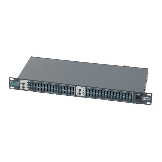
WARNING: When using electrical products, basic cautions should always be followed, including the following: Read these instructions. Keep these instructions. Heed all warnings. Follow all instructions. Do not use this apparatus near water. Clean only with a dry cloth. Do not block any of the ventilation openings. Install in accordance with manufacturer’s instructions. Do not install near any heat sources such as radiators, heat registers, stoves or other apparatus (including amplifiers) that produce heat. - Page 4 ENGLISH Q ™ SERIES EQUALIZERS Thank you for purchasing a Peavey Electronics Q Series graphic equalizer. The Q family features one dual-channel model (Q2151) and one single-channel model (Q1311), both incorporating Peavey’s legendary low noise, low distortion design. These ruggedly constructed Q Series EQs have 20 mm, center-detented control sliders enclosed in metal for durability. These one rack-space units also offer ±12 dB gain control, switchable ±12 dB or ±6 dB frequency band boost/cut and an LED display...
-
Page 5: Front Panel
EQUALIZATION PROCESS Always begin the equalization process with all sliders at their center-detent (flat response) positions. Lower each fader until the feedback frequency is found. Lower the faders in small amounts to avoid adversely affecting sound quality. Likewise, excessive boosting of a frequency may result in feedback. EXERCISE CAUTION WHEN ATTEMPTING TO BOOST FREQUENCIES BELOW SPEAKER SYSTEM TRANSDUCER CUT-OFF. -
Page 6: Rear Panel
frequency bands. They are adjustable within ±12 dB, or ±6dB for improved precision. LOW CUT FILTER This switch activates the low cut filter, which rejects frequencies below 40 Hz. Frequency roll- off is 24 dB per octave with the switch engaged. This filter will operate even with the BYPASS (5) switch engaged. - Page 7 XLR OUTPUT These three-pin male connectors provide balanced output when used with female XLR connectors. (10) TRS BALANCED INPUT These 1/4" tip/ring/sleeve (stereo) jacks provide balanced input when used with TRS connectors and two-conductor shielded cables. When used with mono 1/4" (TS) phone plugs, the input is unbalanced.
-
Page 8: Specifications
SPECIFICATIONS* Filter Q Filter Center Frequencies, Hz Maximum Filter Boost/Cut Output Noise Bypass Mode Filter (Flat) Mode Frequency Response Distortion Input Impedance Output Impedance Maximum Input Level Maximum Output Level Nominal Input / Output Levels Input Headroom Output Headroom Maximum Gain Boost/Cut Low Cut Filter Power consumption... - Page 10 What Peavey Will Do We will repair or replace (at Peavey's discretion) products covered by warranty at no charge for labor or materials. If the product or component must be shipped to Peavey for warranty service, the consumer must pay initial shipping charges. If the repairs are covered by warranty, Peavey will pay the return shipping charges.
- Page 11 Features and specifications subject to change without notice. Peavey Electronics Corporation • 711 A Street • Meridian, MS 39301 (601) 483-5365 • FAX (601) 486-1278 • www.peavey.com ©2002 Printed in the U.S.A. 8/02...
Need help?
Do you have a question about the Q 1311 and is the answer not in the manual?
Questions and answers