Table of Contents
Advertisement
Quick Links
Advertisement
Table of Contents

Related Manuals for Brunton F-5012


Summary of Contents for Brunton F-5012
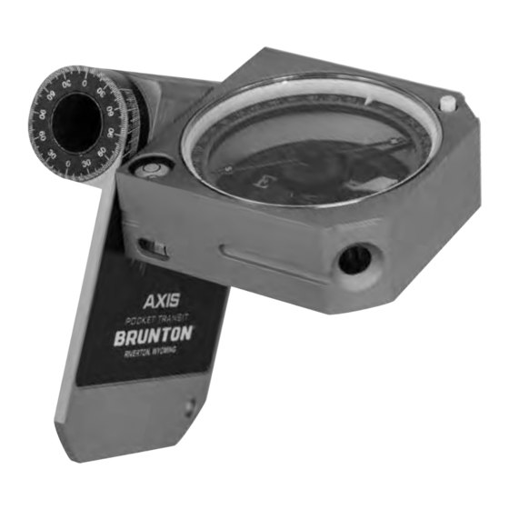
- Page 1 AXIS TRANSIT INSTRUCTION MANUAL EVERY ANGLE, EVERY DIRECTION...
-
Page 2: Specifications
Plunge Angle Accuracy: ±½° WITH 1° GRADUATIONS • To help protect your transit, always store and carry it in its case when not in use. Brunton recommends placing the Axis in its case with the base against the snap (Figure 1) to avoid scratching the lid decal. - Page 3 FIGURE 3 FIGURE 4 Main diagram of Axis components A through K. Diagram of compass face components L through P. Major Axis of Hinge Rotation M. Zero Pin (Compass North) J. Needle Button L. Graduated Circle K. Hinge Block (Adjuster beneath on base) J.
- Page 4 All around the inner compass base is a versatile clinometer circle with 1° increments for measuring vertical angles. The clinometer circle Grooves on both sides of the compass body are for attaching to a Brunton ball & socket tripod mount.
- Page 5 FIGURE 5 FIGURE 7 FIGURE 9 Standard configuration of the Axis lid, ALTERNATE CONFIGURATION of the Axis lid, Rotation of lid/compass face around MINOR AXIS, with detail showing where to read plunge or vertical angle on the lid protractor where rotating around major axis.
-
Page 6: Magnetic Declination
MAGNETIC DECLINATION (or variation). Declination changes with time and location on earth, so it is important to know the current declination for your particular location in order to make accurate compass measurements. Brunton recommends using an online declination calculator such as the National Geophysical Data Center’ s Declination Calculator. - Page 7 5 – MEASURING HORIZONTAL BEARINGS 5.2 – DIRECT READING Field professionals often need to measure the bearing, or compass direction, from their location to a specific landmark or destination. You may notice that East and West appear to be switched when viewing the compass face. Like other pocket transits, the Axis is a direct This might be for navigation, surveying, or triangulation to pinpoint a location on a map.
- Page 8 6 – MEASURING VERTICAL INCLINATION 6. If the Axis is held with the lid right of the compass face in RIGHT-HAND sighting configuration (FIGURE 16), then the SOUTH-SEEKING end of the needle should be read. To measure, record, and map an angle of inclination between two points or along a slope, field professionals measure angles in the vertical FIGURE 16 : RIGHT-HAND sighting configuration of object level with eye, SOUTH-SEEKING end of magnetic needle should be read for plane.
- Page 9 7 – MEASURING STRIKE AND DIP OF A PLANE FIGURES 20A AND 20B : Measurement of strike and dip of a plane in STANDARD CONFIGURATION, using lid to average or extend a planar surface. Planar surfaces are one of the most common features measured and mapped by geologists in the field. Planar surfaces often include bedding planes of layered rock units, faults, joints, axial planes and limbs of folds, and metamorphic foliation.
- Page 10 8 – MEASURING TREND AND PLUNGE OF A LINE 5. DIP ANGLE can be read off of the dials on either side of the hollow hinge, but you must make sure you are reading the dip mark correctly. When the lid is in standard configuration (FIGURES 20A AND 20B), read the dip dial mark where it meets the TOP of the inscribed dip Lines, or lineations, (FIGURE 23) are another common feature measured and mapped by geologists in the field.
-
Page 11: Other Measurements
9 – OTHER MEASUREMENTS FIGURE 24 Measurement of a lineation plunging to the right. Plunge is read where the lid protractor intersects the top of the compass face. Trend RAKE (PITCH) is read from the NORTH-SEEKING end of the needle in this configuration (the N inside the hinge block is a reminder of which end of the Lineations along a planar surface can also be measured using RAKE (also known as pitch). -
Page 12: Reference Material
FIGURE 27 : Using the Axis as a field protractor to measure angles between conjugate fractures or fold limbs. TABLE 10.2 Trigonometry Quick Calculations SIN(Ө) =A/C CSC(Ө) = C/A COS(Ө) = B/C SEC (Ө) = C/B TAN (Ө) = A/B COT (Ө) = B/A A = Side Opposite Angle Ө... - Page 13 The idea of the Axis Transit was first conceived by Lauren Heerschap, a geology instructor in Durango, CO, while teaching field geology to college students. Like most seasoned field geologists, Lauren had learned how to use the standard Brunton transit model as a student, then used it to conduct graduate and professional field research.
-
Page 14: Warranty And Service Information
Brunton Axis Transit. They have been honored to work with the great Hank Iden, who has been inventing and improving Brunton compasses since 1975 in the Riverton, WY facility. It is a dream come true to see the Axis join the lineup of high-quality precision instruments and hopefully revolutionize how field measurements are made! 12 –... - Page 15 Precision Instruments Handmade in Riverton, WY Since 1894 Invented by Real Science Innovations, LLC in Durango, CO in 2014 – Patent Pending 1900 Taylor Avenue Louisville, CO, 80027 800-443-4871 info@bruntongroup.com www.Brunton.com...
Need help?
Do you have a question about the F-5012 and is the answer not in the manual?
Questions and answers