Table of Contents
Advertisement
Quick Links
Advertisement
Table of Contents

Summary of Contents for LUXMATE IRS
- Page 1 LUXMATE for use Instruction manual...
-
Page 2: Table Of Contents
Thank-you for choosing to buy our control unit with the LUXMATE control system. We are convinced you will enjoy using it. To ensure continued satisfaction with the IRS control unit, please read this instruction manual and become familiar with the information it contains. -
Page 3: Safety Instructions
Clean the remote control with a soft, fluff-free cloth, moistened with clean water if necessary. Risk of damage by third party equipment Claims under warranty are no longer valid. Use exclusively LUXMATE equipment. Damage by sunlight Protect the device from exposure to direct sunlight. -
Page 4: Luxmate Philosophy
LUXMATE Philosophy LUXMATE strives to create worlds of adventure with light. Light and glare are decisive factors for the design of a workplace and exert direct influence on well-being, ability to concentrate and efficiency. Using innovative approaches, lighting and room management from LUXMATE focuses on people. -
Page 5: Luxmate Scenes
LUXMATE scene. Every LUXMATE output permanently stores its value for this scene. From that moment on, this scene can be recalled at any LUXMATE IRS in the room. Using the IRS, scenes 1, 2 and 3 can be configured (Basic) and recalled (Basic / Professional / Advanced). -
Page 6: Appearance And Technical Information
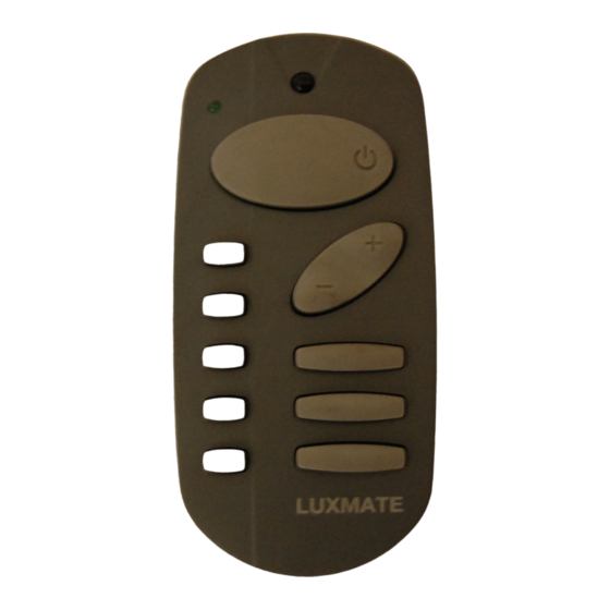
The Remote Control LEDTransmit LEDTransmit diode diode (Broadcast) Come/ Go (on/off) LeaveAdjust key (dimming, up / down) Sectors SectorsScene keysLUXMATE CE: Approval and Conformity This infrared remote control meets the requirements of EU Directives. 89/336/EEC “EMC directive”, 73/23/EEC “Low voltage electrical equipment directive”. Conformity of the remote control with the above directives is confirmed by the CE mark. - Page 7 TV equipment. Note: Dark coloured walls reflect less strongly, which is why it is necessary to optimize the alignment to the sensor when using the IRS. The transmission characteristic of the IRS has the following appearance: Reception range with targets...
-
Page 8: Installation
Insert the batteries supplied into the battery compartment according to the polarity indicated. The IRS is functional when the green LED lights up. Test that the IRS is functioning by pressing any key, e.g. the “Arrive / Leave” key. -
Page 9: Operation
Operation Switching on If the system is switched off (“Absent”), pressing the “Arrive / Leave” key recalls the last setting (which can be a scene or a dimmed scene); pressing a scene key briefly (shorter than 7 seconds) activates the programmed light scene;... - Page 10 (less than 7 seconds). A light scene can be temporarily modified by jointly or individually dimming or switching all the DSI-IRs etc. allocated to the IRS. Programming light scenes: Before programming, set the individual sectors to the required brightness values.
-
Page 11: Settings: Dsi-Ir
A DSI-IR is allocated to an IRS by setting the transmitting code selector switch in the battery compartment of the IRS to the same digit as the rotary switch labelled “IRS” on the DSI-IR. The devices are delivered set to 0. In order to avoid neighbouring IR-Basic facilities from influencing each other it is possible to set one of 7 different infrared transmitting codes ( 0 - 6). -
Page 12: Settings: Dsi-2Ir
5 sector keys (a - e). For example, in order to allocate DSI output 1 of the DSI-2IR to the first sector key of the IRS, the “SECTOR” rotary switch of the DSI-2IR is set to “a”. -
Page 13: Settings: Dsi-Irblc
Function of DSI-IRBLC: The infrared input/balance digital output DSI-IRBLC enables control over the IRS of up to 25 balanced light luminaires with one digital lamp operating device each for the direct and indirect radiating lamp. The IRS can be used to control both the total brightness (INTENS) and the light balance (BALANCE) of the luminaires. - Page 14 5 sector keys (a - e). In order to enable the brightness of the luminaires connected to the DSI-IRBLC to be adjusted, the DSI- IRBLC is allocated (for example) to the first sector key of the IRS: To do this, the “SECTOR” rotary switch of this DSI-IRBLC is set to “a”.
-
Page 15: System Requirements
System Requirements for BASIC DSI- IRED IRED IRED IRED IRxx IREL IREL IREL IREL Master Max. 5 IRED/IREL DSI- IRxx Slave max. infrared line length 50 m DSI- IRxx Slave DSI- IRxx Slave Max. 8 DSI-IRxx DSI- IRxx Important IRED IREL A maximum of 5 Slave... - Page 16 Group III Notes A minimum IR Basic facility consists of one IRS, one IRED or IREL and one DSI-IR, DSI-2IR or mum of 25 lamp operating devices can be controlled per DSI-IR and 2 x a maximum of 25 lam...
- Page 17 Group I Fluorescent lamps T8 (26mm), T5 (16mm) digital electronic ballast, max. 25 pcs. TC-L/TC-DEL/TC-TEL Incandescent lamps/ HV-tungsten-halogen lamps Group II PHD/APDX digital phase dimmer, max. 25 pcs.max. 2 mGroup III max. 2m Gruppe III LV tungsten-halogen lamps max. 230VA digital transformer, max.
-
Page 19: Operation
Operation of LUXMATE Professional/ Advanced Arrive (switching on) If the „Absent“ scene is active, briefly pressing the „Arrive / Leave“ key recalls Scene 1; pressing a scene key briefly (shorter than 7 sec- onds) activates the corresponding room/group scene; in this case any sector selection before pressing the scene key is ignored. -
Page 20: Addressing / Programming
Up to a total of five sectors (a, b, c, d, e) can be defined. Programming the IRS Note on programming the sector keys Allocation of the sector keys of the IRS to the ouput devices or groups is performed using the respective commissioning device. Note on programming the room scenes The different room scenes are programmed with the commissioning devices (LM-EG, LM-CG, LM-MPA/CPA or AD-CG, AD-MPA). - Page 21 Infrared transmitting code Before the allocation of output devices to the IRS the transmitting code switch „IRS“ in the battery compartment of the IRS is set to the required code. The IRS is then allocated as a momentary action switch by means of a commissioning device (LM-EG, LM-CG, LM-MPA/CPA or AD-CG, AD-MPA) (see corresponding commissioning instructions).
-
Page 22: System Requirements
Up to 10 differently configured remote controls can be used in a single room. Notes A minimum Advanced/Professional facility consists of one IRS infrared sensor, one IRED or IREL and one IR device such as LM-IRDSI or LM-2IRDSI, or for Advanced one AD-IRB, together with the associated lamp operating devices and luminaires. -
Page 23: Trouble Shooting
•Has the IRS been allocated to the output devices? •Is the separation between remote control and sensor too great? (see page 7 for max. range of the IRS) •Is there interference from infrared microphones, infrared headphones, projectors, etc. on standby in the room? - Page 24 INTERNATIONAL LUXMATE CONTROLS GmbH Schmelzhütterstrasse 26 A-6850 Dornbirn/Austria Tel. +43-(0)5572-599-0 +43-(0)5572-599-699 luxmate@luxmate.co.at www.luxmate.com INFOLINE Tel.: +43-(0)5572-599-334 Fax.: +43-(0)5572-599-9334 GREAT BRITAIN LUXMATE Limited Thomas House Hampshire International Business Park Crockford Lane Basingstoke RG 24 8 WH +44-1256-707570 +44-1256-707565 luxmate@uk.luxmate.co.at www.luxmate.com SPAIN LUXMATE SL C/Isla de Hierro n°5...
Need help?
Do you have a question about the IRS and is the answer not in the manual?
Questions and answers