Advertisement
Quick Links
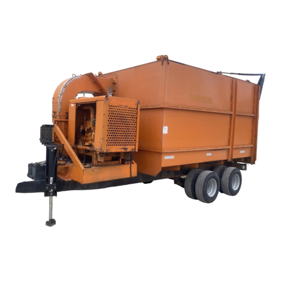
INSTRUCTIONS FOR ASSEMBLING AND OPERATING YOUR GIANT-VAC
MODEL 6600 - 9900 TRUCKLOADER
As you unpack your Giant-Vac truck loader, you will find the following parts:
1 - Power unit with motor and impeller
1 - Ctn. with a nozzle, support band and lower boom
1 - Exhaust stack & elbow combination
1 - Intake hose - 18" diameter
1 - Exhaust hose - 12" diameter
1 - Upper boom
1 - Package of hardware with boom chain
Inspect parts for any damage that may have occurred in shipping. If found, save the packing box and
IMMEDIATELY notify the transport carrier who delivered your machine. They are responsible for
the damage and are the only ones to make any adjustments. Before leaving our plant, we hold all
dimensions to close tolerances, thus, you will have little difficulty in assembling your Giant-Vac Truck
Loader if you follow these steps.
Diesel engine exhaust and some of its constituents are known to the State
of California to cause cancer, birth defects, and other reproductive harm.
As an owner of off-road diesel engine equipment and/or as an employer,
you also may have an obligation under the California Occupational Safety
and Health Act or under Proposition 65 to warn persons exposed to diesel
engine exhaust and /or other Proposition 65 chemicals in and around your
workplace. See California Health and Safety Code section 25249.5, Title
22 of the California Code of Regulations at section 1200, er seq., and Title
8 of the California Code of Regulations section 5194.
ASSEMBLY:
Remove the draw bar, Ref. #1, from the hitch, turn it around so the pintle eye is facing outward. Re-
bolt the draw bar into the hitch at the desired height and length. Remove and discard the shipping leg
at this time, as it is only for shipping purposes. Lower the adjustable leg, Ref. #4, to work in
conjunction with the support jack, Ref. #2, to level the machine. Bolt the exhaust stack and elbow
combination, Ref. #5, onto the top of the blower housing, using three 1/2 x 4 1/2" hex bolts, flat
washers, lock washers and nuts. Position this so the boom holder brackets put the boom, when
installed, over the intake flange. Secure the metal exhaust hose, Ref. #4 to the round end of the elbow
with the squeeze ring. Tighten the bolts to hold the hose in place. Attach the upper boom to the lower
boom, using a 1/2 x 3" hex bolt and lock nut. Then, attach the spring guide to the upper boom, using a
1/2 x 3" hex bolt and lock nut. Remove the 3/4" nut and flat washer from the bottom of the spring
CALIFORNIA PROPOSITION 65 WARNING
ASSEMBLY INSTRUCTIONS
Manual No. 3079076 (1/2002)
Advertisement

Related Manuals for Giant-Vac 6600

Summary of Contents for Giant-Vac 6600
- Page 1 IMMEDIATELY notify the transport carrier who delivered your machine. They are responsible for the damage and are the only ones to make any adjustments. Before leaving our plant, we hold all dimensions to close tolerances, thus, you will have little difficulty in assembling your Giant-Vac Truck Loader if you follow these steps.
- Page 2 Adjust the height of the hose by where you put this end of the chain. CONNECTING TO THE TRUCK: Your Giant-Vac truck loader is very versatile. It tows readily by a truck. CHECK WITH YOUR STATE AND TOWN ORDINANCES FOR TOWING RULES, REGULATIONS AND SAFETY STANDARDS.
- Page 3 SAFETY AND OPERATING INSTRUCTIONS TRAINING: 1. Regard your Giant-Vac as a piece of power equipment and teach this regard to all who will operate this unit. 2. Never allow children or young teenagers to operate the Giant-Vac. 3. Be sure you know how to stop the engine at a MOMENT’S NOTICE.
-
Page 4: Maintenance And Storage
9. After the machine is running, check the adjustment of the chain on the hose support. This is vitally important for ease of operation. To make this check, speed up the engine. You should then be able to push the nozzle to the ground and pull it back up by using three fingers of one hand. If you can not operate the nozzle accordingly, either the chain should be readjusted or the spring tension of the boom assembly changed. - Page 5 Any obligation under this warranty is expressly limited to the replacement or repair, at an authorized servicing Giant-Vac dealer, or at a point designated by us, of such parts as appear to us to have been defective. All defective parts have to be returned freight prepaid before credit will be issued.
- Page 7 PARTS LIST NO. 5773 POWER UNIT REF. PART 6600JD/ 6600PD/ 9900JD/ 6600JDCHW* 6600PDCHW* 9900JDCHW* DESCRIPTION --Asterisk (*) next to ref no. denotes part used on CHW models only-- 10189 Loader base - skid mount 10191 Loader base – skid mount 10205 Loader base –...
- Page 8 REF. PART DESCRIPTION 6600JD/ 6600PD/ 9900JD/ 6600JDCHW* 6600PDCHW* 9900JDCHW* --Asterisk (*) in ref no. column denotes part used on CHW models only-- 27350 Removable side panel for 6 cyl John Deere engine shell 27349 Removable radiator screen for 4 cyl JD/Perkins engine 27350 Removable radiator screen for 6 cyl John Deere engine 31626...
- Page 10 PARTS LIST NO. 5773 DISCHARGE/TRAILER ASSEMBLY REF. PART 6600JD/ 6600PD/ 9900JD/ 6600JDCHW* 6600PDCHW* 9900JDCHW* DESCRIPTION --Asterisk (*) next to ref no. denotes part used on CHW models only-- 24624 Stack, elbow and sq. to round assy. 24625 Stack, elbow and sq. to round assy. 31512 1/2 x 1-3/4”...
- Page 12 PARTS LIST NO. 5722 HOSE SUPPORT BOOM – ALL MODELS REF. PART 6600JD/ 6600PD/ 9900JD/ 6600JDCHW* 6600PDCHW* 9900JDCHW* DESCRIPTION 40107 Boom vertical member 40106 Boom horizontal member 40108 Threaded spring guide 31110 3/4” nut 31370 3/4” flat washer 31332 Boom coil spring 31333 1/2 x 3”...
Need help?
Do you have a question about the 6600 and is the answer not in the manual?
Questions and answers