Advertisement
Instruction Leaflet
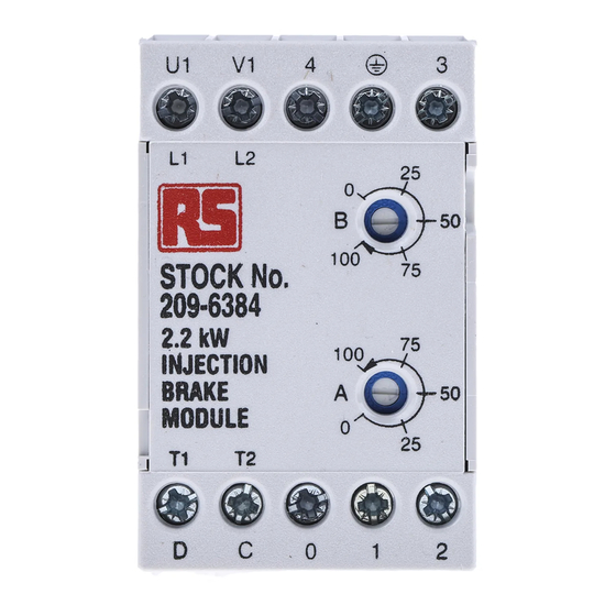
Size 0.25...2.2 kW
1.1...5.5 kW
Figure 1
Recommended connection for use with induction motors with DOL starting
General
RS DC Injection-Brake Modules provide a method of rapidly
stopping production and machine tool processes smoothly.
Designed to replace mechanical brakes these modules will brake
three-phase induction motors from 0.25 up to 5.5 kW in 2 module
sizes. These compact DIN-rail mounted modules have the
advantages of separate braking torque and braking time-out
adjustment;
fast
initiation
requirements and simple connection.
of
function,
no
maintenance
DC Injection-brake modules
Adjustment procedure
1. Set potentiometer A (Braking time-out) and potentiometer B
(Braking torque), both fully counter clockwise.
2. Increase potentiometer B in a clockwise direction until the required
braking performance is obtained by starting and stopping the
motor.
3. Adjust potentiometer A until Braking Relay (MB) opens just after
the motor has stopped (braking complete).
Note The above should be carried out for the maximum operational
load that the motor is likely to experience with the motor at
operating temperature.
Issued March 2023
RS
stock no. 209-6384
8461
CE.DRW
209-6407
Advertisement
Table of Contents

Related Manuals for RS PRO 209-6384

Summary of Contents for RS PRO 209-6384
- Page 1 Issued March 2023 8461 DC Injection-brake modules CE.DRW Instruction Leaflet Size 0.25...2.2 kW stock no. 209-6384 1.1...5.5 kW 209-6407 Figure 1 Recommended connection for use with induction motors with DOL starting General Adjustment procedure RS DC Injection-Brake Modules provide a method of rapidly 1.
-
Page 2: Adjustment Ranges
Suggestion for initial setting (initial factory setting) Isolated relay contact with rating AC 250 V, 2 A; 250 VA The above values are approximate values only Technical specifications Electrical RS Stock no. 209-6384 RS Stock no. 209-6407 Rated Voltage 2AC 400 V +10-15 % Rated Frequency 50/60 Hz ±2 %... -
Page 3: Planning The Installation
Planning the installation Intended use: Safety: RS DC Injection-Brake Modules are equipment to be mounted in a RS DC Injection-Brake Modules are very reliable due to the relatively suitable enclosure (e.g. equipment cabinet) as part of a machine or small number of electronic components used. However, it is not electrical system. - Page 4 EC directives and regulations 'CE' marking Low-voltage directive It is the responsibility of the user to ensure that the complete The 'CE' marking of the RS DC Injection-Brake Modules is at the date at which this Product Manual is issued valid for the EU DIRECTIVES installation adheres to the LOW-VOLTAGE DIRECTIVE.
- Page 5 Figure 2 Alternative connection for use with induction motors with DOL starting Figure 3 Alternative connections without a braking contactor (only suitable for fractional-horsepower motors) Figure 4 Recommended connection combined with star-delta starting 8461 - 5 - 1005-101/04 PB-RS-8461-16.03.2023...
- Page 6 Figure 5 Recommended connection as combined soft-start and injection brake using RS Soft-Start Modules 212-8683 and 212-8699 Figure 6 Alternative connection with PLC-control as combined soft-start and injection brake using RS Soft-Start Modules 212-8683 and 212-8699 The information provided in RS instruction leaflet is believed to be accurate and reliable, however RS Components assumes no responsibility for unaccuracies or omissions, or for the use of this information, and all use of such information shall be entirely at the user's own risk.
Need help?
Do you have a question about the 209-6384 and is the answer not in the manual?
Questions and answers