Advertisement
Quick Links
Vibrati Punk Console Build Instructions
To find out more about the Vibrati Punk Console or buy a kit go to:
lushprojects.com/vpc
Step 1 – Introduction
To build the kit you'll need:
-
Vibrati Punk Console Kit
-
Solder
-
Wire Cutters
-
Soldering Iron
-
PP3 9 Volt battery
-
Wire stripper or sharp knife
If you don't know how to solder, or want a refresher this cartoon book
How To Do
It" (http://lushprojects.com/vpc/build/FullSolderComic_EN.pdf) by Mitch Altman, Andie
Nordgren and Jeff Keyzer is a great introduction. This book covers all the soldering skills you need to
build the Vibrati Punk Console. Take some time to read the book if you need an introduction to
soldering.
Page | 1
"Soldering Is Easy, And Here's
Advertisement

Summary of Contents for Lush Projects Vibrati Punk Console
- Page 1 It” (http://lushprojects.com/vpc/build/FullSolderComic_EN.pdf) by Mitch Altman, Andie Nordgren and Jeff Keyzer is a great introduction. This book covers all the soldering skills you need to build the Vibrati Punk Console. Take some time to read the book if you need an introduction to soldering.
- Page 2 Step 2 – Mounting the Integrated Circuit Sockets The Vibrati Punk Console is built around a single printed circuit board (PCB). All the components are placed on one side of the circuit board (the “component side” or top). The component side has labels showing where to place components.
- Page 3 Step 3 – Add Resistors The Vibrati Punk Console uses four Variable Resistors to control the sounds, but at this stage we are just going to add the fixed resistors. Fixed resistors are small cylindrical components with coloured bands that indicate the value of their resistance. Resistors can go in to the circuit either way around.
- Page 4 Step 4 – Add Small Capacitors The Vibrati Punk Console uses 6 small capacitors. These are of a type called “Ceramic Discs” and look like brown discs with leads coming off one side. This type of capacitor can go in the circuit either way round.
- Page 5 Step 5 – Add Big Capacitors The Vibrati Punk Console has 2 larger capacitors of a type called “Electrolytic”. These have a polarity, a positive and a negative lead, and have to go in the circuit right way round. There are two ways to determine the polarity of this type of capacitor.
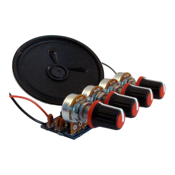
- Page 6 Step 6 – Add the Variable Resistors There are four variable resistors that control the sound of the Vibrati Punk Console. These are soldered in a row on one edge of the circuit board so they can be mounted on a control panel if desired.
-
Page 7: Step 7 - Connect The Speaker
Step 7 – Connect the Speaker Cut the grey wire provided in half. These two lengths are used to connect the speaker. Strip about 5mm of insulation off each end of wires. You can strip the wire using a special wire stripping tool, or by gently scoring the insulation with a sharp knife and pulling the end off. - Page 8 Step 8 – Connect the Battery Clip and Switch To complete this step you will need the battery clip, red wire and switch. Take the battery clip and solder the red wire from the clip to one tag on the switch (use the same technique as you did for soldering to the speaker in Step 7).
- Page 9 I know you want to switch the Vibrati Punk Console on, but carefully checking the circuit now will save a lot of problems later. Take a while to carefully check the circuit and fix any errors. Carefully inspect all the components and connections.
- Page 10 Step 10 – Inserting the Integrated Circuits (ICs) In this step we’ll take the two Integrated Circuits (ICs) and insert them in to the sockets on the board. To get the ICs in to the sockets you’ll probably need to bend the pins so they are at right- angles to the body.
- Page 11 Are the ICs and large capacitors in the right way? If you put the ICs in backwards you may have destroyed them :-( Replacement ICs are easy to obtain though :-) Hopefully you are now the proud owner of a Vibrati Punk Console. Have fun. Page | 11...
Need help?
Do you have a question about the Vibrati Punk Console and is the answer not in the manual?
Questions and answers